Ill post some of what I found in my backup ( I have more stuff spread out but this should start us off )
First some pics:
This is not mine, but it might be useful:
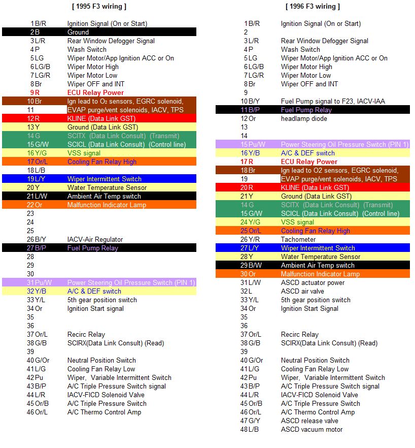
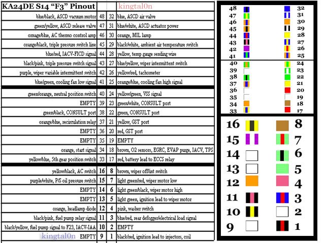
F3 plug ID, I made this by looking at an actual harness
Now a text document I have, I didn't make it (I dont think so anyways, I dont remember):
These instructions will allow you to wire a 1995-1996 SR20DET S14 blacktop (WC ecu, black or red sticker) To a 1995/1996 240sx. The wiring for a 96 240sx is different than a 95 wiring, however, my 96's only differences were not important in the wiring so i wired it like a 95.
1995 sr to 1995 240sx, S14 blacktop w/ vtc.
This is just the F3 plug wiring. you still need to lengthen the maf wire, o2 wire, and some other misc bullshit.
The only diagrams I used to make this paper were my S14Pinout-Colors.jpg, which matched my KA harness pinout (verified before starting) and my SR20 ECU pinout XLS file on my website.
l/y = wiper switch is present on s14 sr harness pin 47 moved to pin 27
moved black/red from left to right 9 to 1
moved blue/red (defroster) present in sr moved to pin 3 from i think 12
took pins 10 and 11 from ka harness and put into sr harness same places (empty in sr harness)
took pin 16 from ka and put into 16 in sr harness
moved pin 25 from ka to sr harness it was empty in sr harness cooling fan
oraNGE BLUE ON sr harness in pin 37 is for the low cooling fan relay, so pulled it out and soldered it to pin 41 on the sr harness, which is green/black useless. So sr pin 37 solder to pin 41. lose wire from 41. 37 also is no longer needed (empty)
the other orange blue wire at pin ?? is the start wire. find the s14 ecu pinout and follow the start signal wire to the f3 plug. its orange blue. that wire gets pulled out, and soldered to pin 34 in the sr f3 plug. thats your start signal. it might need to be pinned in using the orange wire off the ka harness i did do that.
the blue/red from pin 27 on thye sr harness goes to: no where?
I cut it and soldered the blue/yellow wire (wiper intermitten switch) to the bluered at pin 27. I moved the blue/red from 27 to no where?
tied black pink (pinned in from ka) and yellow/black (pinned in from ka) together. this turns on a/c
yank the black/yellow from pin 35 on the sr harness. thats your fuel pump relay wire. Tie it to the black/pink wire you pinned in at pin 11 on the sr harness.
Find the brown wire (sr harnes) around pin 20~. Pull it out.
Find the black/yellow wire (sr harness) in pin 18. pull it out.
Install the just removed brown wire into pin 18. this is your o2 sensor 12v.
The black/yellow wire you removed from pin 18, is your IACV wire (sr harness) I tested myself with a multi. Tie it to your already pinned in black/yellow at pin 10 (sr harness)
Pin 21 (sr harness) is orange. Thats your MIL wire. Movve it to pin 30 (sr harness) there you go working MIL.
pin 24 is red (sr harness) thats your "thermisistor control aplifier" whatever pull it out.
Pin 26 (sr) is green/white.
Pin 46 (sr) is blue/black. Thats your tachometer signal. It goes to pin 26. Pull the g/w from 26 out and replace it with the pin 46, blue/black.
pin 45 (sr) is yellow. its your temp gauge. move it to pin 28 (sr). multi verified to the harness.
pin 29 (sr) is green/orange. this is your neutral switch wire verified to pinout.
move it to pin 40. at 40 you will find a wire g/y, this is your "ac relay" wire.
clear out pins 39 to 35 jus tin case. remove them. sr harnes.
now move the purple wire from pin 48 (Sr harness) to pin 42. thats for your wiper. not power steering.
move pin 44 (sr) yellow/green to pin 24 (empty now) thats your speedo wire.
The pin 44 that used to be y/g should be for some IACV shit. but i dunno what. "FICD?" it says.
This could be incomplete beware.