Quote:
Originally Posted by LoSt180

Something that no one ever seems to acknowledge is that a lot of these "builds" are simply over sizing their fuel pumps in general. Figure I'd share some of the items I've come across over the years.
|
There are three issues to consider that most will not realize immediately
1. Boost pressure reference causes fuel pressure to rise with boost- which will reduce pump flow capacity. SO a 500hp pump at 40psi is only like a 400hp pump at say 60psi or whatever. The HP supported drops with boost increasing.
2. Voltage is a powerful influence on pump HP supply. Most people assume they always have 14.5v or so at the pump but it might only be 12.5v usually once warmed up fully. Fuel pumps produce heat and will heat the fuel gradually.
3. Fuel pump heating is a potential problematic for large pumps and especially dual pumps. A single aeromotive/AEM 340lph pump for example over the course of an hour can raise 10 to 15gallons of fuel temp significantly even with engine off. I recommend PWM control for primary fuel pump to reduce heating for daily drivers. But this is extra cost and complexity unwanted in a majority of 4-cylinder sub 500hp setups which typically use small enough single pumps to run constantly just fine.
Finally a tuning tip. I always tune the engine using lowest voltage at the fuel pump possible. Always turn off alternator during WOT to achieve this conditional.
The reason for this is, you want the fuel system tuned to alternator failure just in case the alt actually does fail at WOT you won't lose the engine. If the pump can't support the power at 12.0 or 12.5v then its too small. People often rely on and tune their power output using 14v or even 16v at the fuel pump are asking for catastrophic failure which happens eventually.
I always configure alternator "turn off" at WOT for every engine now,
its a default setting for some stand-alone computers
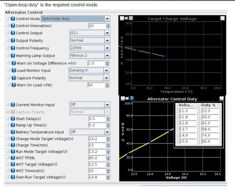
We target 12.5v at WOT using alternator duty control. Makes the engine safe even if the alternator fails, pump output drops to a pre-determined safe level.
This is also important in general for other electronics such as injectors. An alternator at high RPM may provide constantly changing voltage... e.g. 14.54, 14.46, 14.39, 14.52, 14.42, etc... The voltage is changing rapidly over the course of RPM change, it is not constant or stable. This will influence all other systems, coil dwell and injector delay to name the important two. This leads to 'wavy' torque curves, oscillations in the engine output to the tires, instead of a clean smooth curve. Once you lower the voltage demand to near battery voltage (often 12.45 to 12.55v) the system voltage can remain steady, and clean, using the battery as a high capacitance (large capacitor) which stabilizes the injector delay and coil dwell targets... resulting with a much smoother running engine if the alternator is incapable or somehow unable (it happens frequently on custom setups, not so badly with OEM nissan stuff) to maintain a steady voltage. SR20 I don't generally have a problem letting the alt work like stock but its still a valuable tuning tool to keep the pocket, be aware of the influence of wavering/wavy changing voltage signals and how that will scale non-linearly between intervals of ECU cell to cell programming. In other words, no injector delay map is going to perfectly correct for offsets, it might be close but there are still non linear differences cell to cell. So anytime the cell moves from one to another such as during changing voltage, it will "step more and more" Into a neighboring cell value, the imperfection is included in the step quantity as error. if the signal is oscillating each crossover will generate error term component with a direction in the new cells value, leading to a frequency response dynamical system of dependency for which state space vectors are ultimately defining system behavior, they can be predicted and compensated or neglected causing overshoot and possibly increased oscillation frequencys, uncontrolled frequency oscillation in voltage systems where it isn't wanted. Which is why I think many OEM alternators and current control strategies work well and custom versions fall apart quickly: The late model OEM likely fine tunes their frequency response characteristics for current and voltage regulator systems, whereas a hobbyist is more likely to attach a random alternator on something with questionable ground pathways and perhaps poorly insulated and expect the ECU to regulate it properly, automatically at high RPM to maintain a steady voltage. Even if the alternator is capable of such a thing the very installation influence is such a large part of that possibility it is never safe to assume it's going to work properly without being tested and verified first. And that it can't possibly fail or that the fuel pump can support the engine in case it falls to 12.0v one day unexpectedly. Which will happen eventually, all alternators eventually fail, they can't last forever. The baseline assumption from engineering safety point of view is that, the alt can fail at any minute, so our entire system needs to be configured to allow the engine safe operation when this event happens.