so i went through this whole wiring diagram and fixed the few flaws in the original wiring. no offense to the OP b/c he did a great job and spent alot of time on it. as i said there were a few flaws (most minor and have been covered)...a couple work...but aren't how it was intended to be wired. here is what i've typed out. you will only need to solder a few wires. the rest just depin the JDM harness and then one by one pull the pins from the USDM harness and repin them into the proper position in the JDM harness.
i am about to do this next week and hope i don't run into issues. the ONLY thing i have setup different is the thermo. i am not sure where to source a
Thermo control amp as the original writeup didn't say much about this. i bypassed this in the wiring but would like to put it back in as it would make the wiring absolutely 100%. i assume that this just means whenever the a/c button is on the a/c compressor is on?
here is my wiring. Hope this helps someone.
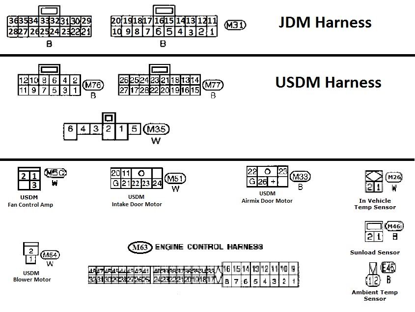
M76 & M77 Climate Control Plugs
Move USDM To JDM USDM Color
1 - 22 L/OR (blue w/ orange stripe)
2 - 31 L/Y (blue w/ yellow stripe)
3 - 30 L/R (blue w/ red stripe)
4 - 22 L/W (blue w/ white stripe) *
5 - 21 L/B (blue w/ black stripe)
6 - 30 L (blue) **
7 - 6 G/OR (green w/ orange stripe)
8 - 5 G/Y (green w/ yellow stripe)
9 - N/A N/A
10 - N/A N/A
11 - 4 G/W (green w/ white stripe)
12 - N/A N/A
13 - 19 OR/L (orange w/ blue stripe) (95-96 Y/B)
14 - 12 L/OR (blue w/ orange stripe)
15 - 13 R/L (red w/ blue stripe)
16 - 14 R/Y (red w/ yellow stripe)
17 - 20 B (black)
18 - 2 LG/W (light green w/ white stripe)
19 - 1 PU (purple)
20 - 3 G/B (green w/ black stripe)
21 - 28 Y/B (yellow w/ blue stripe)
22 - 8 B/R (blue w/ red stripe)
23 - 7 R/W (red w/ white stripe)
24 - 32 Y (yellow)
25 - N/A N/A
26 - 27 P/L (pink w/ blue stripe)
27 - N/A N/A
* solder this wire to the L/OR wire that you inserted into pin 22 of the JDM DCC plug
** solder this wire to the L/R wire that you inserted into pin 30 of the JDM DCC plug
M31 JDM DCC Plug Extra Wiring
Pin JDM Color
11 OR/G (orange w/ green stripe) Connect this wire to a constant 12 volt source. You can find one at your radio.
16 L/W (blue w/ white stripe) Run a wire down to the blower motor plug and connect to M54 pin #2 L/W (blue w/ white stripe)
17 Y (yellow) Run a wire down to the M63 main ECU connector and connect to pin #28 Y (yellow) (If you have a swapped motor this will change. refer to your individual wiring for this. It should be the one wire water temp sensor) 19 L/B MA26 Engine Temp. Sensor
23 G/Y (green w/ yellow stripe) Run this wire to the M51 Intake Door Motor Plug and pin into pin #23 (there is no wire here so you will need to pinn it yourself)
24 Y (yellow) Run this wire to the M51 Intake Door Motor Plug and pin into pin #22 (there is no wire here so you will need to pinn it yourself)
25 OR/L (orange w/ blue stripe) This is connected to the OR/L wire on the in cabin temp sensor
26 OR (orange) This is connected to the orange wire on the sunload sensor
29 B/Y (black w/ yellow stripe) Connect this wire to pin #2 on M26, M46 and E46. All three wires are B/Y (black w/ yellow stripe) you will also be connecting the black wire from the air mix door motor plug M33 as noted below.
34 OR/B (orange w/ black stripe) This is connected to the OR/B wire on the ambient temp sensor
M35 Fan Switch Plug
Move USDM To JDM USDM Color
1 - 9 L (blue) - (you will need to solder this connection to the existing blue wire in pin 9 of the JDM M31 plug.) This also needs to be connected to pin #1 of the Fan Control Amp. (it's either blue ot blue w/ white stripe depending on the year of the FCA) Run a heavy gauge wire down to where you mounted the Fan Control Amp.
M50 Fan Control Amp Plug
From Pin To JDM USDM Color
1 L (blue or blue w/ white stripe) Run Heavy Gauge Wire Up To DCC & Connect To Pin #1 Of M35 Fan Switch Plug
2 10 L/Y (blue w/ yellow stripe) Run wire to JDM DCC and connect to pin 10 of JDM DCC plug
3 B (black) Ground To Chasis
M33 Air Mix Door Plug
From Pin To JDM USDM Color
+ 33 L/OR (blue w/ orange stripe) Run a wire from the + pin on the m33 connector to pin #33 P (pink) on the JDM DCC
G 29 B (black) Run a wire from the G pin on the M33 connector to pin #29 B/Y (black w/ yellow stripe) on the JDM DCC