|
|||||||
| Home | Rules & Guidelines | Register | Member Rides | FAQ | Members List | Social Groups | Calendar | Mark Forums Read |
| Tech Talk Technical Discussion About The Nissan 240SX and Nissan Z Cars |
|
|
Thread Tools | Display Modes |
 11-12-2007, 12:22 PM
|
#1 |
|
Zilvia Junkie
 
Join Date: Dec 2002
Location: san diego area - esco
Posts: 461
Trader Rating: (0)
  Feedback Score: 0 reviews
  |
S15 Cluster Sig Converter
THIS DOES NOT COVER FITTING IT IN THE DASH
S15 Cluster Converter The issue with the S15 cluster being used in a S13(91+)/S14 is the speedo signal and temp gauge signal. First here is the schematic:  Here is the part list: Part Value C1 0.01U C2 0.01U C2A 1U C2B 1U C3 0.1U C4 1U C5 0.1U C6 0.22U C7 0.22U C8 0.1U C9 0.1U IC1 LM340H-05 or LM140A-05 IC2 LM340H-12 or LM140A-12 IC3 74LS109N IC4 LM331N IC5 LM2917 R1 100K R2 10K R3 100K R4 470 R5 100K R6 47 R7 6.8K R8 10K R9 6.8K R10 5K All resistors are 5% or less and all the caps are ceramic or tantalum. This is needed to keep the temp coef down. It can get hot under the dash. Now lets get into what everything does. -Power and logic levels- IC1 and IC2 are the volatge regulators. IC2, C7 and C8 regulate the input voltage to 12v which is used for power to the LM2917 and LM331. IC1,C6 and C5 then regulate that to 5v for logic high and power for the 74LS109N. -Input frequency to voltage converter- IC5, R1, R2, R4, C9, C1, C2A, C2B are used to convert the speedo input from a zero crossing signwave to a voltage. C9 is a filter for the input since its really noisy. R4 is for voltage dropping sice the LM2917 has a 7.6v internal zener regulator. The output voltage is defined by Vout = Vcc * Fin * C1 * R1 * K where K = 1 and VCC = 7.6 The output ripple is defined by Vripp = (Vcc / 2) * (C1/(C2A+C2B)) * (1 - ((Vcc * Fin * C1) / I3)) where VCC = 7.6, I3 = 180uA, Fin = input freq 4.5hz(1mph) - 810hz(180mph) -Voltage to frequency converter primary- IC4, R3, C3, C4, R5, R6, R7, C2, R9, R10 are used to convert the voltage back to a frequency. That frequency is defined by Fout = (Vin/2.09) * ((R9+R10)/R5) * (1/ (R7 * C2)) Where Vin = Vout from the F-to-V converter. R10 is adjustable so the conversion factor can be fully adjusted. R6 and C4 are used to keep the internal referance stable. R3 and C3 are for input filtering. -Signal conditioning- IC3 and R8 are used to form the 50% duty cycle square wave. IC3 is a dual J/K flip flop so the output will change its state once per pulse and dividing the primary output freq by 2. This is needed because the output pulse width from the LM331 is too small. Output here should be 12.5hz/mph -ECU speed signal- I did not put this part in because i dont need it and i dont care about it. But if you want to make it you can. It will be the same as the Voltage to frequency converter primary section except for different values for R9 and R10. The output will be fed into the second half of IC3 (remember its a DUAL j/k ff). The output of IC3B will need to be 0.5hz/mph (still cant figure out why the ECU would want such a low resolution) The input of this whole stage would be fed from the R3 and R2 junction. Nothing bad happens from not having this, except a no speed sig fault and never have a fuel cut. That basicly covers to Converter portion. Remeber to use good parts and to use actual measuments for the formulas and calibration. -Wiring- This can all be had from the FSMs, except for the speedo hookup. S13 have 2 wires for the speedo. On a 89 S13 they are pin 6 (yellow/blue) and pin 12 (yellow/black). One of these needs to be hooked to ground. Its doesnt matter which one but i used pin 12. Pin 6 will now the the input for the converter. For the temp guage to work correctly see post #28 Let me know if you have any questions or problems. Remember this is all free and if you screw something up, its not my fault. Yes it all works in my car. 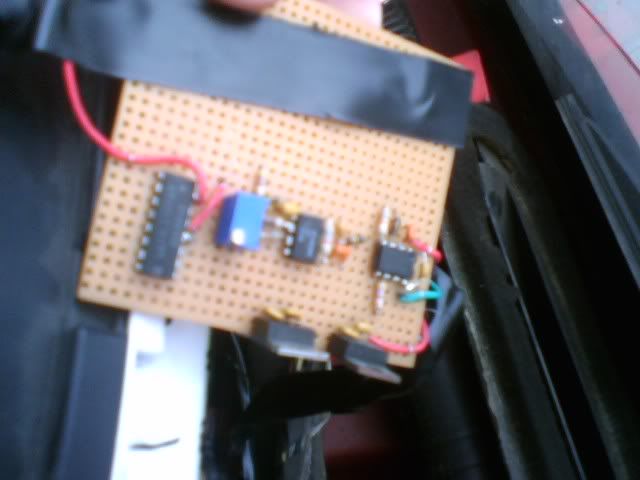 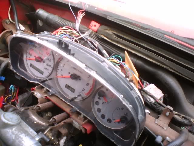 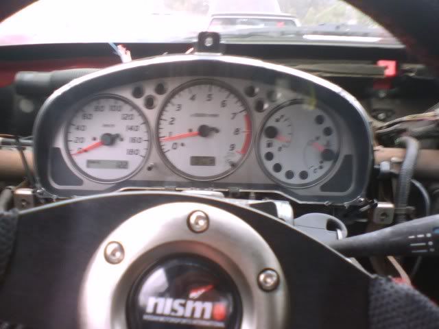  Last edited by xsparc; 10-14-2008 at 05:41 PM.. |

|

|
| Sponsored Links |
| Bookmarks |
| Thread Tools | |
| Display Modes | |
|
|


 Threaded Mode