|
|||||||
| Home | Rules & Guidelines | Register | Member Rides | FAQ | Members List | Social Groups | Calendar | Mark Forums Read |
| Tech Talk Technical Discussion About The Nissan 240SX and Nissan Z Cars |
 |
|
|
Thread Tools | Display Modes |
 11-12-2007, 12:22 PM
|
#1 |
|
Zilvia Junkie
 Join Date: Dec 2002
Location: san diego area - esco
Posts: 461
Trader Rating: (0)
  Feedback Score: 0 reviews
  |
S15 Cluster Sig Converter
THIS DOES NOT COVER FITTING IT IN THE DASH
S15 Cluster Converter The issue with the S15 cluster being used in a S13(91+)/S14 is the speedo signal and temp gauge signal. First here is the schematic:  Here is the part list: Part Value C1 0.01U C2 0.01U C2A 1U C2B 1U C3 0.1U C4 1U C5 0.1U C6 0.22U C7 0.22U C8 0.1U C9 0.1U IC1 LM340H-05 or LM140A-05 IC2 LM340H-12 or LM140A-12 IC3 74LS109N IC4 LM331N IC5 LM2917 R1 100K R2 10K R3 100K R4 470 R5 100K R6 47 R7 6.8K R8 10K R9 6.8K R10 5K All resistors are 5% or less and all the caps are ceramic or tantalum. This is needed to keep the temp coef down. It can get hot under the dash. Now lets get into what everything does. -Power and logic levels- IC1 and IC2 are the volatge regulators. IC2, C7 and C8 regulate the input voltage to 12v which is used for power to the LM2917 and LM331. IC1,C6 and C5 then regulate that to 5v for logic high and power for the 74LS109N. -Input frequency to voltage converter- IC5, R1, R2, R4, C9, C1, C2A, C2B are used to convert the speedo input from a zero crossing signwave to a voltage. C9 is a filter for the input since its really noisy. R4 is for voltage dropping sice the LM2917 has a 7.6v internal zener regulator. The output voltage is defined by Vout = Vcc * Fin * C1 * R1 * K where K = 1 and VCC = 7.6 The output ripple is defined by Vripp = (Vcc / 2) * (C1/(C2A+C2B)) * (1 - ((Vcc * Fin * C1) / I3)) where VCC = 7.6, I3 = 180uA, Fin = input freq 4.5hz(1mph) - 810hz(180mph) -Voltage to frequency converter primary- IC4, R3, C3, C4, R5, R6, R7, C2, R9, R10 are used to convert the voltage back to a frequency. That frequency is defined by Fout = (Vin/2.09) * ((R9+R10)/R5) * (1/ (R7 * C2)) Where Vin = Vout from the F-to-V converter. R10 is adjustable so the conversion factor can be fully adjusted. R6 and C4 are used to keep the internal referance stable. R3 and C3 are for input filtering. -Signal conditioning- IC3 and R8 are used to form the 50% duty cycle square wave. IC3 is a dual J/K flip flop so the output will change its state once per pulse and dividing the primary output freq by 2. This is needed because the output pulse width from the LM331 is too small. Output here should be 12.5hz/mph -ECU speed signal- I did not put this part in because i dont need it and i dont care about it. But if you want to make it you can. It will be the same as the Voltage to frequency converter primary section except for different values for R9 and R10. The output will be fed into the second half of IC3 (remember its a DUAL j/k ff). The output of IC3B will need to be 0.5hz/mph (still cant figure out why the ECU would want such a low resolution) The input of this whole stage would be fed from the R3 and R2 junction. Nothing bad happens from not having this, except a no speed sig fault and never have a fuel cut. That basicly covers to Converter portion. Remeber to use good parts and to use actual measuments for the formulas and calibration. -Wiring- This can all be had from the FSMs, except for the speedo hookup. S13 have 2 wires for the speedo. On a 89 S13 they are pin 6 (yellow/blue) and pin 12 (yellow/black). One of these needs to be hooked to ground. Its doesnt matter which one but i used pin 12. Pin 6 will now the the input for the converter. For the temp guage to work correctly see post #28 Let me know if you have any questions or problems. Remember this is all free and if you screw something up, its not my fault. Yes it all works in my car. 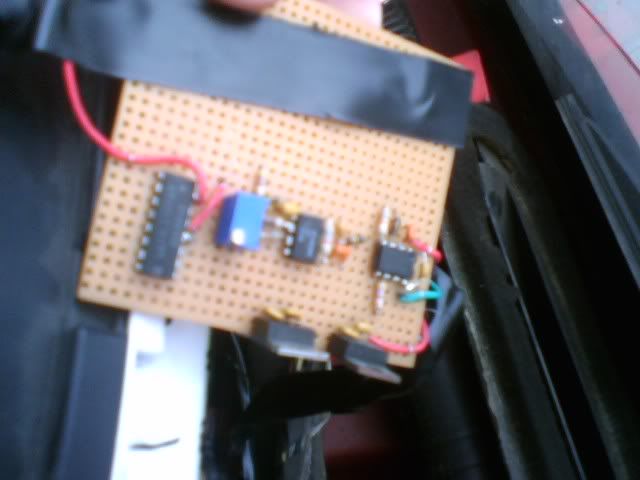 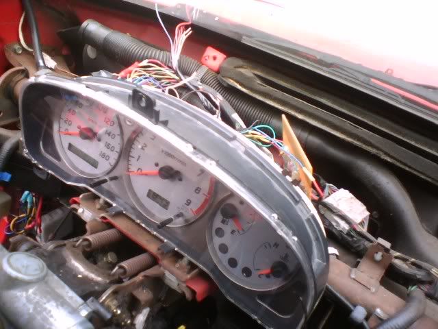 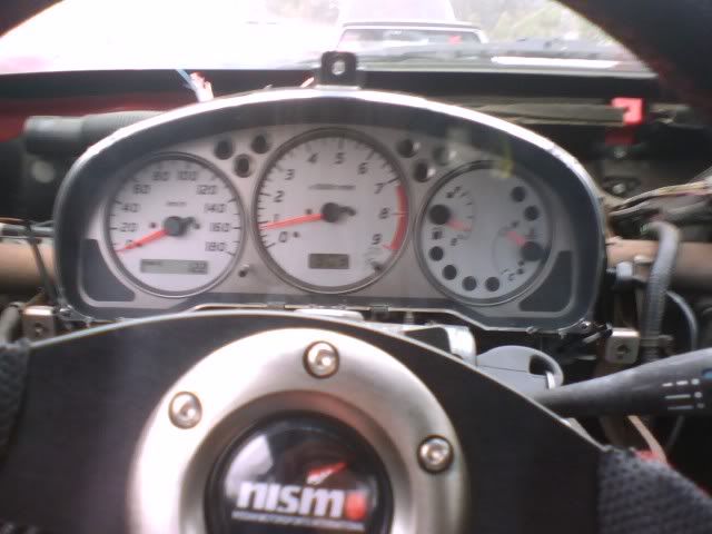  Last edited by xsparc; 10-14-2008 at 05:41 PM.. |

|

|
| Sponsored Links |
|
11-12-2007, 10:50 PM
|
#4 |
|
Zilvia Addict
 Join Date: Feb 2006
Location: myrtle beach,south carolina
Posts: 932
Trader Rating: (0)
Feedback Score: 0 reviews
|
we want plug and play.. i will pay for an s14 setup.. just give my the paypal buddy.
__________________
Mouth of the South There are a few mailboxes that have been looking at me the wrong way, lately. Nothing goes unchecked. 
|
|
|
|
|
11-12-2007, 10:57 PM
|
#5 |
|
Zilvia Junkie
Join Date: Dec 2002
Location: san diego area - esco
Posts: 461
Trader Rating: (0)
Feedback Score: 0 reviews
|
hey i was sooo happy the gas light worked, the one in my original cluster didnt work for sooo long.
im not going to be making these for anyone. if someone else wants to do it then go for it. |
|
|
|
|
11-12-2007, 11:34 PM
|
#7 |
|
Zilvia Addict

Join Date: Mar 2004
Location: Los Angeles, CA
Age: 45
Posts: 734
Trader Rating: (0)
Feedback Score: 0 reviews
|
Amazing...
But a little too technical for me... Marco from SR20 store will do it for $300...
__________________
http://respectvolkracing.blogspot.com/ |
|
|
|
|
11-12-2007, 11:47 PM
|
#8 |
|
Zilvia Addict
Join Date: Feb 2006
Location: myrtle beach,south carolina
Posts: 932
Trader Rating: (0)
Feedback Score: 0 reviews
|
i wonder if there is any east coast guys who can do it. like south east guys.
__________________
Mouth of the South There are a few mailboxes that have been looking at me the wrong way, lately. Nothing goes unchecked.
|
|
|
|
|
11-13-2007, 11:02 AM
|
#9 |
|
Nissanaholic!
 Join Date: May 2005
Location: East Bay
Age: 40
Posts: 2,110
Trader Rating: (0)
Feedback Score: 0 reviews
|
i can probably make this plug and play but they'll be slightly diff for s13 and s14, let me look up the cost of these buggas
__________________
 parking lot pimpin... Seller Feedback here: http://www.zilvia.net/f/showthread.p...ight=pbcstylez |
|
|
|
|
11-13-2007, 08:25 PM
|
#11 |
|
Wow mad props. I read on the other post that you made it yourself... thats very impressive, where did you go to school for this?
I don't suppose the chips are hard to find although some maybe harder than others, so I assume most everything, except maybe one of the chips, can be purchased at radio shack. And Just for comparison of the $300 that Nikeboy said, how much did all the parts cost you? Last edited by NvIs; 11-13-2007 at 09:24 PM.. |
|
|
|
|
|
11-14-2007, 03:40 PM
|
#12 |
|
Zilvia Addict
Join Date: Feb 2006
Location: myrtle beach,south carolina
Posts: 932
Trader Rating: (0)
Feedback Score: 0 reviews
|
what all would be major diffrences in the s14. i wonder if a computer shop could put this together. they soder boards and chips together every day.. could someone possibly point me in the right direction to having someone do this..
__________________
Mouth of the South There are a few mailboxes that have been looking at me the wrong way, lately. Nothing goes unchecked.
|
|
|
|
|
11-14-2007, 07:21 PM
|
#13 |
|
Nissanaholic!
Join Date: May 2005
Location: East Bay
Age: 40
Posts: 2,110
Trader Rating: (0)
Feedback Score: 0 reviews
|
the issue here is how nice do you want it to be?
sure i can make one on a breadboard similar to xsparc, but i was actually looking to cut out PCBAs vs using a breadboard. you can do this yourself just go to fry's electronics to get the bread board than order your ICs and passive components through arrownac.com
__________________
parking lot pimpin... Seller Feedback here: http://www.zilvia.net/f/showthread.p...ight=pbcstylez |
|
|
|
|
11-15-2007, 12:46 PM
|
#15 |
|
Nissanaholic!
Join Date: May 2005
Location: East Bay
Age: 40
Posts: 2,110
Trader Rating: (0)
Feedback Score: 0 reviews
|
the mph conversion is done using the steps he provided, the only additional steps would be to hookup the ecu speed sensor
__________________
parking lot pimpin... Seller Feedback here: http://www.zilvia.net/f/showthread.p...ight=pbcstylez |
|
|
|
|
11-16-2007, 12:52 PM
|
#18 | |
|
Nissanaholic!
Join Date: May 2005
Location: East Bay
Age: 40
Posts: 2,110
Trader Rating: (0)
Feedback Score: 0 reviews
|
Quote:
__________________
parking lot pimpin... Seller Feedback here: http://www.zilvia.net/f/showthread.p...ight=pbcstylez |
|
|
|
|
|
11-21-2007, 11:08 AM
|
#21 |
|
Zilvia Junkie
Join Date: Dec 2002
Location: san diego area - esco
Posts: 461
Trader Rating: (0)
Feedback Score: 0 reviews
|
im not gonna say what it cost me to make it, dont wanna hurt anyones profits. but i was no where near what race shops charge for speed signal converters. the most expensive thing was the cluster itself, $150. if you look up the parts i used on digikey.com youll see what it cost me.
making a NICE plug and play one is where the extra cost will come in. getting a profesional board made out where i am is about $100, plus the cost of the nissan connectors and the case might make it expensive. I didnt go to school for any of this. granted ive been messing with electronics for about 15 years. first i read the FSMs, then i used a o-scope to look the signal from the speed sensor and measured it for mph whith the car on jackstands. then i used a function generator to find the right freqs for the cluster (i got the signal type from the fsm). google is a wonderful thing, i just looked up frequency-to-voltage converters and voltage-to-freqency converters (since i needed 2 back to back, freq-voltage-voltage-freq), read all the spec sheets, did the math that they said to do for the conversions. then built it and tested it. everything just takes effort and time, thats how mountains are turned to dust |
|
|
|
|
11-21-2007, 08:24 PM
|
#23 | ||
|
Quote:
 Quote:
I saw you didn't have a case on yours, but wouldn't the heat build up from behind the dash effect diodes or resistors even though of there 5% reduced? Do you have any more pics of the wiring? Thanks  |
|||
|
|
|
|
11-21-2007, 09:25 PM
|
#24 |
|
Zilvia Junkie
Join Date: Dec 2002
Location: san diego area - esco
Posts: 461
Trader Rating: (0)
Feedback Score: 0 reviews
|
my cluster came with the plugs and a few inches of wire. the s13 plugs wont fit in the s15 cluster.
the parts i used have a high heat tolerance, upwards of 140c, so heat really isnt an issue. i didnt put a case on one because i didnt have one, i just covered it in hot glue so it wouldnt short out on anything. |
|
|
|
|
11-23-2007, 01:13 AM
|
#25 | |
|
Quote:
Thanks for the Schematics and the reply. If you don't mind me asking where did you acquire the S15 gauge cluster. |
||
|
|
|
|
11-23-2007, 01:43 AM
|
#26 |
|
Post Whore!
 
Join Date: May 2006
Location: San Diego, CA
Posts: 9,135
Trader Rating: (19)
Feedback Score: 19 reviews
|
looks great, and all the research is done. I used to be an Aircraft Elec Tech back in the day, makes me happy to see that people still use O-scope's and sig gens to solve problems
Great work ~
__________________
 Jordan Innovations has a new web site! www.JordanInnovations.com -- All your favorite FD Pro Drifters love it, trust me -- www.JordanInnovations.com |
|
|
|
|
03-05-2008, 08:34 PM
|
#28 |
|
Zilvia Junkie
Join Date: Dec 2002
Location: san diego area - esco
Posts: 461
Trader Rating: (0)
Feedback Score: 0 reviews
|
Ok i got the temp guage working for me. If your temp guage is reading max hot then try this.
I dont know what the normal op temp for the 240 is but im guessing its about 90-110c since the thermistat opens around 70c. I ran the car up to 97C and took a measurement of the sender, mine read 24 ohms. then i ran it up to 115C, the sender then read 17ohms. So we want the guage to read in the normal position at 24ohms and about 3/4 at 17 ohms. Now the fun part... remove the board from the back of the s15 cluster and flip it over. 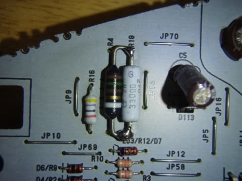 Locate R19, its a large 330ohm resister near the top left. This is the temp guage ref resistor, since the guage is reading high, we need to lower this. You can replace it or put another one in parallel. I found that if you add a 150 ohm resister in parallel it will read just about right on target. You can adjust it if you want to find a good spot for you. I first tried another 330ohm, but it didnt read hot till around 125c. If you guage works fine then you dont need this, maybe i just had a bad guage or something since the s13 and s15 senders have the same ranges according to the FSM. Last edited by xsparc; 10-14-2008 at 05:45 PM.. |
|
|
|
|
08-12-2009, 04:05 AM
|
#29 |
|
Hi there, I am new to this forum and love what you have done with this sig converter!, I am in the process of doing this myself but have a question about the output.
 Here in New Zealand we measure speed in Km/hr not miles and I see you have set this for miles/hr. in the first post you said "R10 is adjustable so the conversion factor can be fully adjusted." does this mean that I can adjust this to make the output accurate for Km/hr? if so how do I do that? Thanks Here in New Zealand we measure speed in Km/hr not miles and I see you have set this for miles/hr. in the first post you said "R10 is adjustable so the conversion factor can be fully adjusted." does this mean that I can adjust this to make the output accurate for Km/hr? if so how do I do that? Thanks |
|
|
|
|
|
08-12-2009, 04:10 AM
|
#30 |
|
Post Whore!
 
|
Instead of soldering the resistor in, could have simply swapped the original sensor for the s15 sensor. Granted it's cheaper to solder in the resistor, it may be easier for those who prefer not to modify the cluster.
Somewhat old post but fantastic breakdown and explanation. Edit: Looks like the S14 KA temp sensor works perfect. Last edited by xpertsnowcarver; 07-16-2011 at 03:57 PM.. |
|
|
|
|
| Bookmarks |
| Thread Tools | |
| Display Modes | |
|
|


 Linear Mode

