|
|||||||
| Builds (and builds only) Got a build thread? It goes here, build threads anywhere else on the forum will be locked and never moved. |
 |
|
|
Thread Tools | Display Modes |
 02-01-2013, 03:01 PM
|
#1741 | |
|
Zilvia.net Advertiser
 
Join Date: Oct 2006
Location: Normal, IL
Age: 50
Posts: 2,946
Trader Rating: (163)
  Feedback Score: 163 reviews
|
Quote:
__________________
  Follow Along For My Latest Work Follow Along For My Latest Work My Portfolio My Portfolio Please Share Please Share Check Out My Builds Check Out My Builds
|
|

|

|
| Sponsored Links |
|
02-01-2013, 06:24 PM
|
#1743 | |
|
Zilvia.net Advertiser
Join Date: Oct 2006
Location: Normal, IL
Age: 50
Posts: 2,946
Trader Rating: (163)
Feedback Score: 163 reviews
|
Quote:
__________________
Follow Along For My Latest WorkMy PortfolioPlease ShareCheck Out My Builds
|
|
|
|
|
|
02-01-2013, 06:29 PM
|
#1744 | |
|
Zilvia Member
 Join Date: Feb 2008
Location: Jacksonville, FL
Age: 38
Posts: 165
Trader Rating: (13)
Feedback Score: 13 reviews
|
Quote:
|
|
|
|
|
|
02-17-2013, 09:30 PM
|
#1746 |
|
Zilvia.net Advertiser
Join Date: Oct 2006
Location: Normal, IL
Age: 50
Posts: 2,946
Trader Rating: (163)
Feedback Score: 163 reviews
|
I know it's going to seem like I'm lying here, but I had some spare time to work on the car today
 I'm working on the air conditioning setup at the moment:   My quest for a clean tidy engine bay has led me to doing a "tucked" air conditioning setup. I don't really like the idea of lines going everywhere in the bay. So I'm going to simplify it by running the lines out of the compressor directly to some custom bulkheads on the firewall. I can run the lines down the same path as my heater hoses alongside the block. Typically the firewall fittings are at each end of a giant loop that takes place in the engine bay. I will essentially relocate that loop to behind the dash and down the inside upper portion of the passenger fender. Then the dryer and condenser will be up front out of site behind the bumper. I want to use all XRP air conditioning hose and fittings. Which means I have to convert everything over to o-ring pilot fittings. Since I bought an aftermarket dryer and condenser, I had the choice to get them with o-ring pilot ports... so those were no big deal. However, I had to figure out what to do with the compressor, evaporator and the ports at the firewall. I'm still in the middle of all of this, but I'll show you my progress so far. First thing was to figure out how to modify the evaporator to work in the "tucked" setup. As it sits from the factory, the evaporator hard lines come out through the firewall. These have to go bye-bye since I'm going to use the firewall locations for my compressor lines. Which means that the connections for the evaporator lines will now need to be done inside the car instead of at the firewall. So I cracked the evaporator plastic housing open to see what I was up against. The evaporator core sits in the middle of the housing as seen below. You can also see where the hard lines exit the housing and normally would protrude through the firewall: 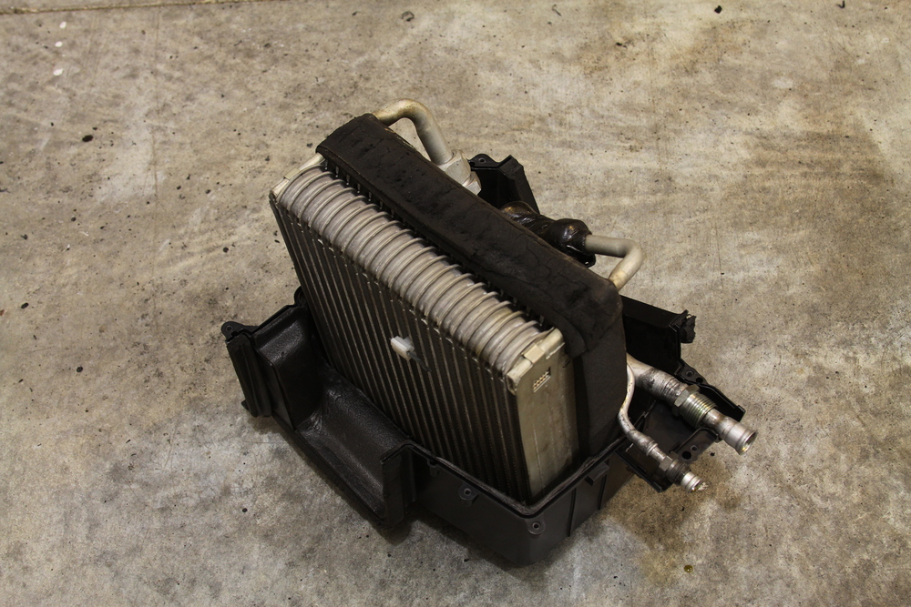 As luck would have it, the evaporator is square. I rotated the evaporator core, inside the housing 90 degrees, so that the hard lines would now point down over the passenger foot well. This would allow me to do my connections inside the car and leave me room on the inside of the firewall for some custom bulkheads. I cut off the plastic protrusions that held the OEM hard lines in place: 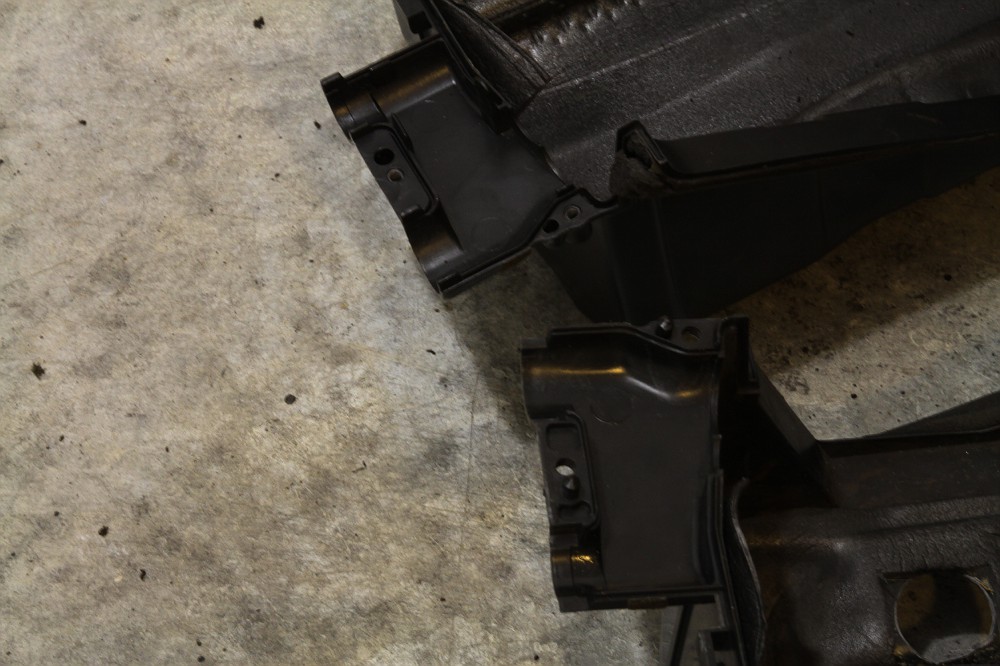 Housing back together... I will simply seal over that figure 8 shaped hole with some thin ABS plastic and epoxy: 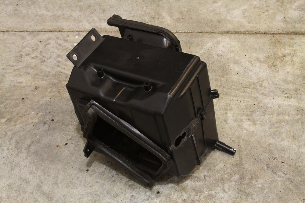 I cut the hard lines down so that the new 90 degree fittings would hug the housing as close as possible. As mentioned, these are going to exit right above the passenger's feet. So I don' want them hanging down where they are going to get kicked. Had some aluminum male o-ring pilot fittings welded on:   I hogged out an area in the bottom of the housing for these to exit:  Some closed cell foam on the inside around the fittings and some machined 90 degree o-ring pilot fittings... this part is complete: 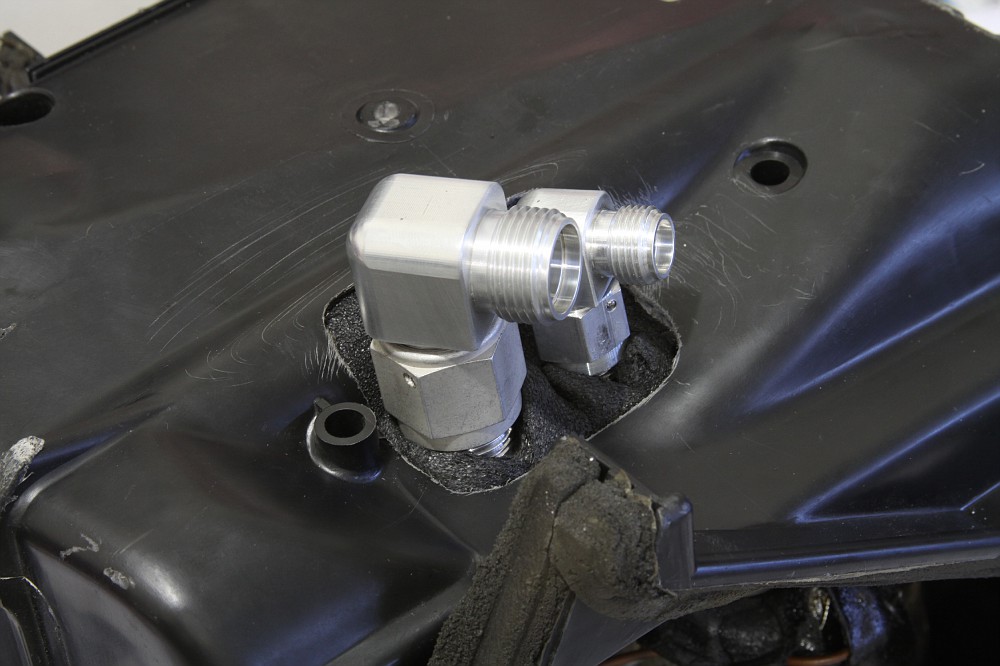 Test fit back in the car... they really don't hang down lower than the surrounding items:  Second order of business are the bulkheads for the compressor lines. It will be a o-ring pilot #10 and a #8 on the firewall. Unfortunately the two holes on the firewall are huge. Had I known I was going to do a tucked setup, I would have welded those closed and made new smaller holes for a pre-made bulkhead. Oh well, time to do something slightly custom and make it work. I bought one of the aforementioned bulkheads from Vintage Air just so I could use the male-to-male fittings. This is what they look like once pulled off the Vintage Air firewall plate:  I figured I would do somewhat of the same setup I did for my heater hose bulkheads... custom machined aluminum plates that would cover the OEM holes and house the male fittings. I came up with these:  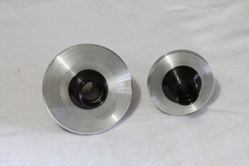  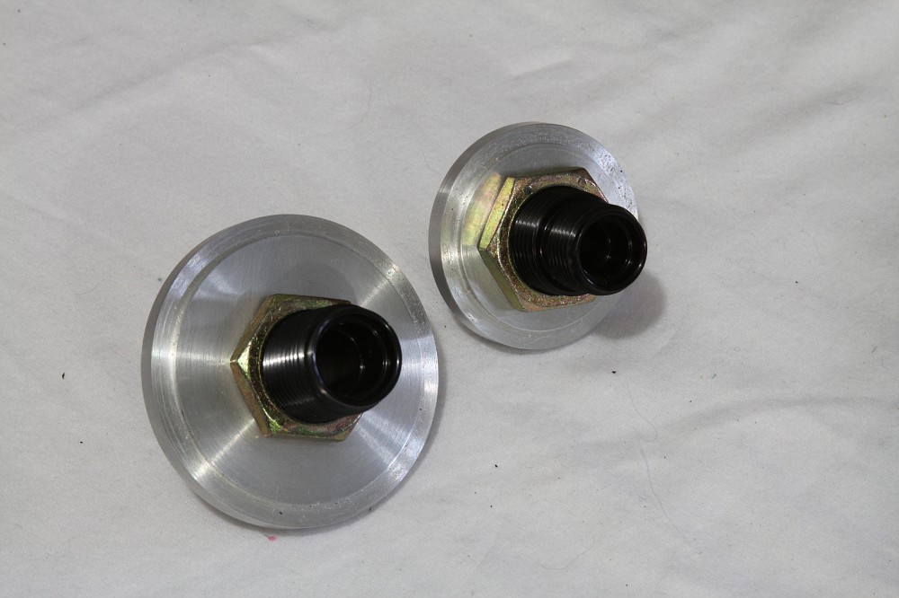 Coated with the some black epoxy paint: 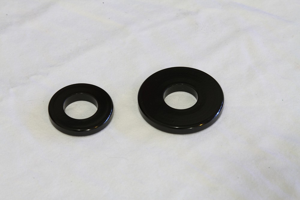 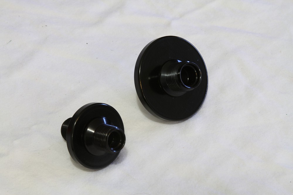 Mounted in the car:   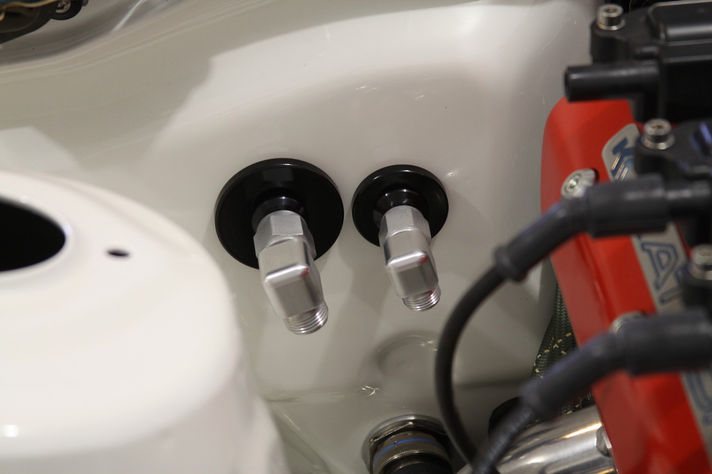 This is what I'm looking at inside the cabin:   I now need to get all of the XRP AC hoses and fittings ordered up so I can start mocking everything up. I also need to buy a CTS-V compressor. I have both a C5 and C6 compressor and neither one of those are going to work. The C6 compressor fittings exit out the side into the frame rail. There's not enough clearance by a long shot. The C5 compressor fittings exit out the back. But by the time I add a compressor o-ring pilot adaptor block, the fittings will hit the #2 primary on the header. The CTS-V compressor angles the fittings out the side and angled up.. perfect!... I think!?!?! Once I have the compressor squared away, I can make the two compressor lines for the bay, the lines inside the cabin and the lines down the fender to the front of the car.
__________________
Follow Along For My Latest WorkMy PortfolioPlease ShareCheck Out My Builds
Last edited by Broadfield; 02-18-2013 at 08:04 PM.. |
|
|
|
|
02-17-2013, 10:01 PM
|
#1748 |
|
Post Whore!
Join Date: Jan 2009
Location: Definitely NOT FL....
Age: 32
Posts: 2,504
Trader Rating: (25)
Feedback Score: 25 reviews
|
your paint looks like powdercoat. Also, what's the purpose of the rubber mat on the inside around the bulkhead connectors?
__________________

|
|
|
|
|
02-17-2013, 10:40 PM
|
#1749 |

|
Bravo! I have been reading this thread for quite some time and lurking around. I figured it was time to join up on this site. Its nice to see dedication and care go into the fine details. It's nice to know there are other people out there with the same OCD as me. Where perfect just is the only way to do something. Where there is no such thing as cutting corners. I look forward to seeing more of this car as you progress. Well Done. SUBSCRIBED.
__________________
"I'm gonna go home and sleep with my wife." |
|
|
|
|
02-18-2013, 12:42 AM
|
#1750 | |
|
Leaky Injector
|
Quote:
 Untitled by gnakata2007, on Flickr Here is a pic of the lines that Fueled Racing made for my set up.  Untitled by gnakata2007, on Flickr Edit: my mistake Toby - I see that the slight angle upwards is what it seems what you are looking for, which my first picture shows.
__________________
91 Z32 TT, 92 Z32 TT, 90 240 LSX in progress, 09 GT-R, 18 Honda Ridgeline Last edited by Turbozx; 02-18-2013 at 12:53 AM.. Reason: Correct mistake |
|
|
|
|
|
02-18-2013, 07:28 AM
|
#1751 | |
|
BANNED
 |
Quote:
|
|
|
|
|
|
02-18-2013, 05:59 PM
|
#1755 | |
|
Post Whore!
Join Date: Jan 2009
Location: Definitely NOT FL....
Age: 32
Posts: 2,504
Trader Rating: (25)
Feedback Score: 25 reviews
|
Quote:
__________________
|
|
|
|
|
|
02-18-2013, 06:45 PM
|
#1756 | |||
|
Zilvia.net Advertiser
Join Date: Oct 2006
Location: Normal, IL
Age: 50
Posts: 2,946
Trader Rating: (163)
Feedback Score: 163 reviews
|
Quote:
Quote:
Quote:
Nice build by-the-way... I was checking your thread out a couple weeks ago.
__________________
Follow Along For My Latest WorkMy PortfolioPlease ShareCheck Out My Builds
|
|||
|
|
|
|
02-18-2013, 08:12 PM
|
#1757 | |
|
Leaky Injector
|
Quote:
 Untitled by gnakata2007, on Flickr As the photo is crappy, here are the numbers in the picture The numbers are 20938668 MC447180-7813 10S17F Denso  CTS V AC Info by gnakata2007, on Flickr  AC PART NUMBER INFO by gnakata2007, on Flickr
__________________
91 Z32 TT, 92 Z32 TT, 90 240 LSX in progress, 09 GT-R, 18 Honda Ridgeline |
|
|
|
|
|
02-19-2013, 08:26 AM
|
#1759 | |
|
BANNED
|
Quote:
|
|
|
|
|
|
03-01-2013, 11:23 AM
|
#1760 |
|
|
Just saw some pics from ur fotki album..was the wiring from chase bays not done careful? It looks that u might have some troubles starting up the engine.
Last edited by georgegto; 03-01-2013 at 02:40 PM.. |
|
|
|
|
03-01-2013, 07:07 PM
|
#1763 | |
|
Zilvia.net Advertiser
Join Date: Oct 2006
Location: Normal, IL
Age: 50
Posts: 2,946
Trader Rating: (163)
Feedback Score: 163 reviews
|
Quote:
__________________
Follow Along For My Latest WorkMy PortfolioPlease ShareCheck Out My Builds
|
|
|
|
|
|
03-02-2013, 02:11 AM
|
#1764 |
|
|
I'm referring to pictures like this
ImageUploadedByTapatalk1362215372.650137.jpg Cut wire from the injector plug etc |
|
|
|
|
03-02-2013, 02:37 AM
|
#1765 | |
|
Post Whore!
 
Join Date: May 2006
Location: San Diego, CA
Posts: 9,135
Trader Rating: (19)
Feedback Score: 19 reviews
 |
Quote:
 Wut.
__________________
 Jordan Innovations has a new web site! www.JordanInnovations.com -- All your favorite FD Pro Drifters love it, trust me -- www.JordanInnovations.com |
|
|
|
|
|
03-02-2013, 07:27 AM
|
#1766 | |
|
Zilvia.net Advertiser
Join Date: Oct 2006
Location: Normal, IL
Age: 50
Posts: 2,946
Trader Rating: (163)
Feedback Score: 163 reviews
|
Quote:
This is a "build", so not all of the pics I take are representative of the final outcome/product. I assure you the harness that is sitting on the car now is good-to-go.
__________________
Follow Along For My Latest WorkMy PortfolioPlease ShareCheck Out My Builds
|
|
|
|
|
|
03-05-2013, 09:42 AM
|
#1767 | |
|
BANNED
|
Quote:
With your 6060 conversion, did you guys do the slip yoke conversion (link below), or just keep that flange style output shaft? 2010 SS TR6060 into 4th Gen FBody (PICS) - Page 3 - LS1TECH |
|
|
|
|
|
| Bookmarks |
| Tags |
| chase bays, ls3, s13, sikky, toby broadfield |
|
|


 Linear Mode

