|
|||||||
| Chat General Discussion About The Nissan 240SX and Nissan Z Cars |
|
|
Thread Tools | Display Modes |
 07-21-2008, 08:54 AM
|
#11 |
|
Zilvia Junkie
 Join Date: Aug 2007
Location: Birmingham, AL
Posts: 423
Trader Rating: (6)
  Feedback Score: 6 reviews
|
Wiring
Now this wiring thing is a pain int he fucking ass. However, I think I amstarting to figure it out. I would love to be able to beat this thing with a hammer and make the wires work but that is not going to happen.
I am using an EZ Wiring Harness and between their manual (which sucks butt) a painless manual (which is much more thorough) and an FSM I have come up with the following diagram that should depict how to get power to the harness. Now I have not included switches and all that jazz but I will as this little project evolves. I will even include pictures but for now this is what I have for the start up and charging system. Some of my arrows may be pointed the wrong way but I am pretty sure I got it right. If you know what you are doing with wiring like this please feel free to comment or lend advice. I Would love to turn this little section of my build into a how to, for guys that want to do this kind of stuff int he future. I always see it done or alot of questions asked, but have never seen a thorough how too. Red = Power (However each type of marked power has its own wire as depicted in the picture). Black = Ground Purple = IGN Switch Start Dark Grey = Alternator Excitor PowerWires Explained: Battery Pos - Starter Pos Post Alt Pos - Alternator Boot 8 Gauge Power - 100 Amp Maxi Fuse (Used in place of Fusible Link) Alternator Boot - Maxi Fuse Maxi Fuse - Solenoid Power on Harness (This is where the Harness gets power from) Alternator Excitor From Fuse Panel - Alternator An Additional wire is added from boot-alternator terminal Alternator is Grounded to Engine Block Ground is Ground Starter Relay Ground Power Constant from fused Wire to Battery Purple Ignition Switch from fuse box to Relay From Relay to Starter Signal. Maxi Fuse replaces Fusible Links at 100 Amps Rating 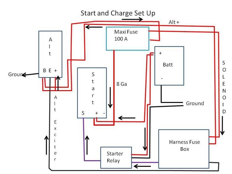 |

|
| Bookmarks |
|
|


 Threaded Mode