|
|||||||
| Tech Talk Technical Discussion About The Nissan 240SX and Nissan Z Cars |
 |
|
|
Thread Tools | Display Modes |
 01-16-2007, 09:21 AM
|
#61 | |
|
Post Whore!
 
Join Date: Jan 2005
Location: Everywhere
Age: 40
Posts: 5,427
Trader Rating: (9)
  Feedback Score: 9 reviews
|
Quote:
Carlos |
|

|

|
| Sponsored Links |
|
01-16-2007, 12:43 PM
|
#64 | |
|
Zilvia FREAK!
 
Join Date: May 2005
Location: Las Vegas
Age: 42
Posts: 1,003
Trader Rating: (1)
Feedback Score: 1 reviews
|
Quote:
Nice build, I've heard of SR's in E30's but never RB series engines. Can't wat to see to final product. |
|
|
|
|
|
01-16-2007, 01:10 PM
|
#65 |
|
Post Whore!
|
excellent attention to detail on this project, good luke and be sure to dyno and time the car as many ways as possible.

__________________
Like Me on FaceBook !
|
|
|
|
|
01-17-2007, 02:29 AM
|
#66 |
|
Nissanaholic!
 
Join Date: Dec 2002
Location: Camp Snake Bite, CA *RIP*
Posts: 2,356
Trader Rating: (0)
Feedback Score: 0 reviews
|
Looking at these pictures, i'm so glad I decided against RB in the e30.
Props to you boss. I couldn't go through the fabwork headache. And for those of you that don't know... I parted my car and built this... 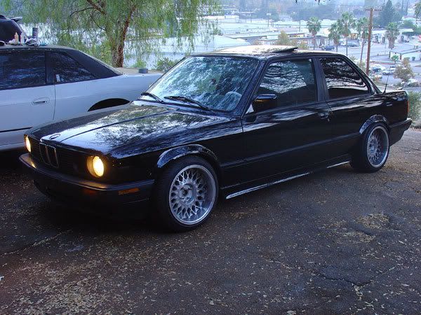
__________________

|
|
|
|
|
01-17-2007, 10:58 PM
|
#67 |
|
Zilvia Junkie
 
Join Date: Apr 2004
Location: buffalo,ny
Age: 43
Posts: 541
Trader Rating: (0)
Feedback Score: 0 reviews
 |
OK, worked on the tunnel today... well, removing it... We are going to make a custom tunnel for the transmission as well as the exhaust. Probably just formed mild stell. We may make it a removable doghouse kind of thing.
From engine bay: 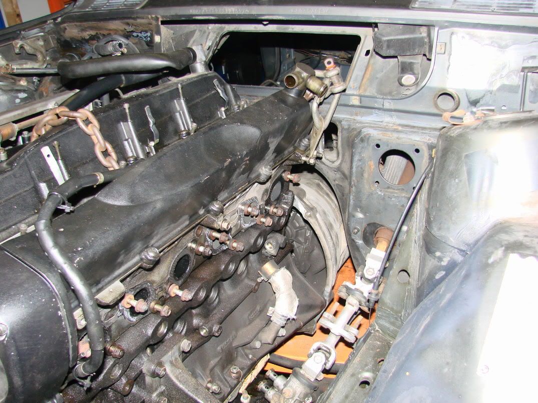 Yeah, you've stood in your engine bay, but have you ever done this? 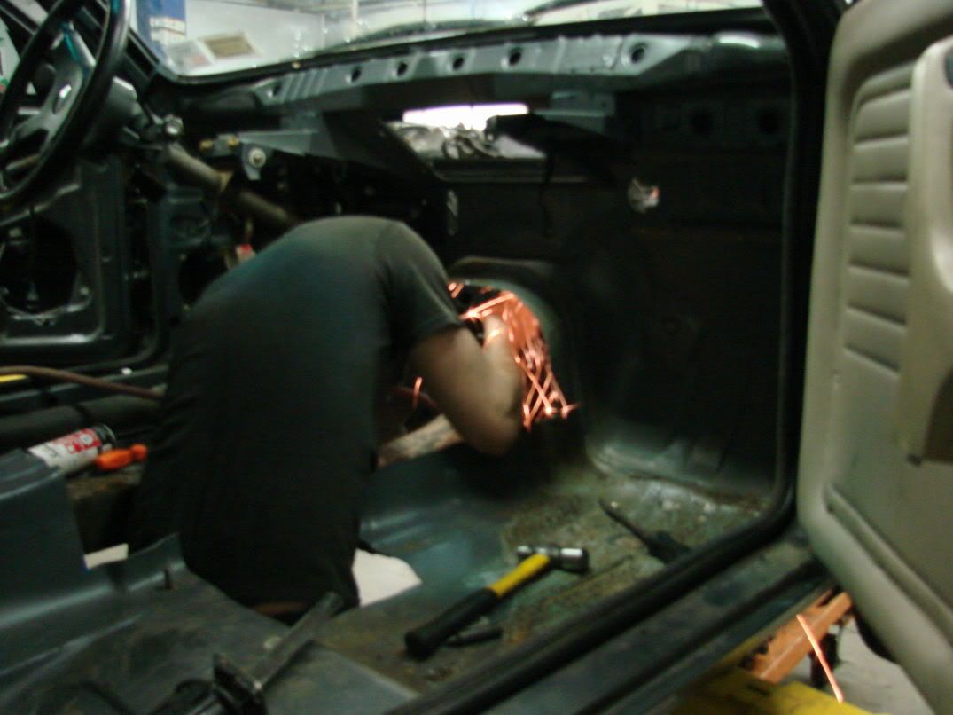 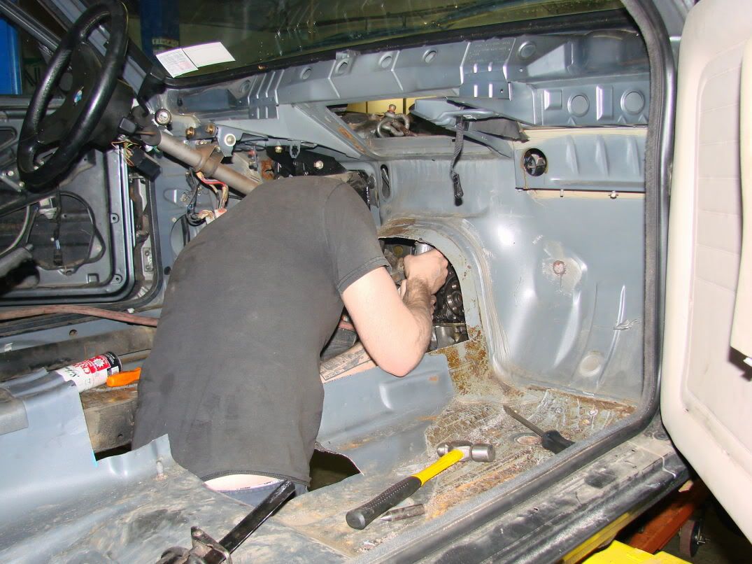 Needs a bit more trimming. Just a little bit... 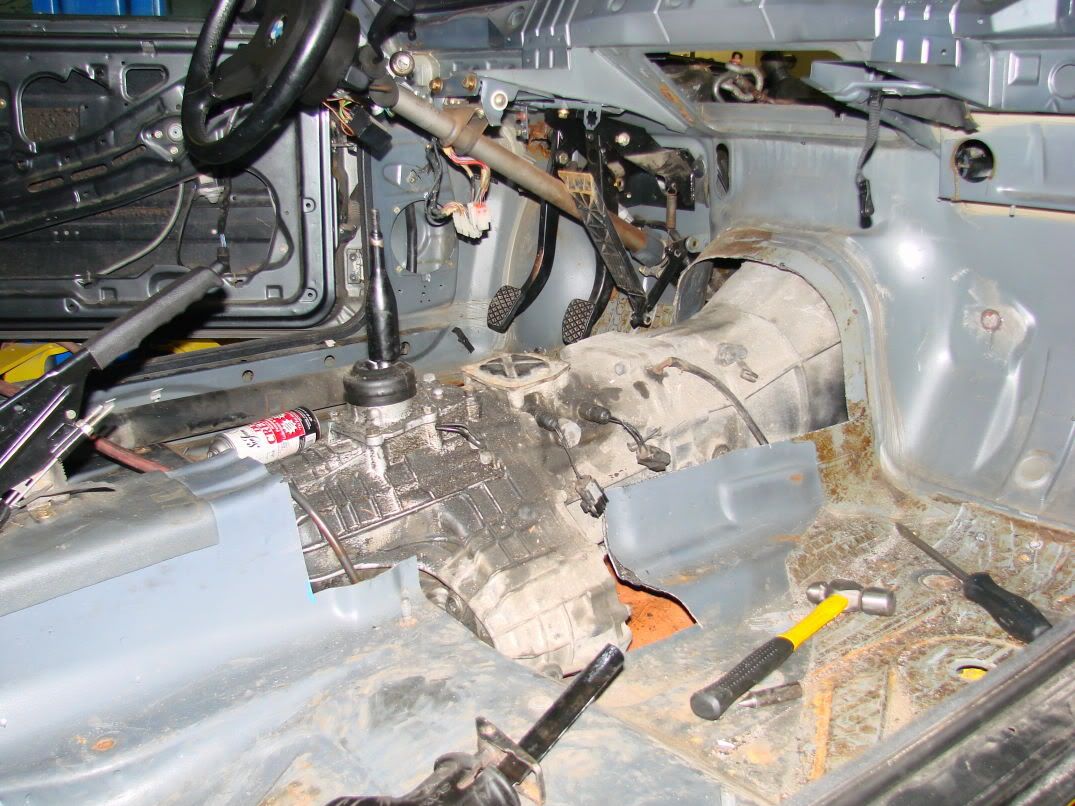 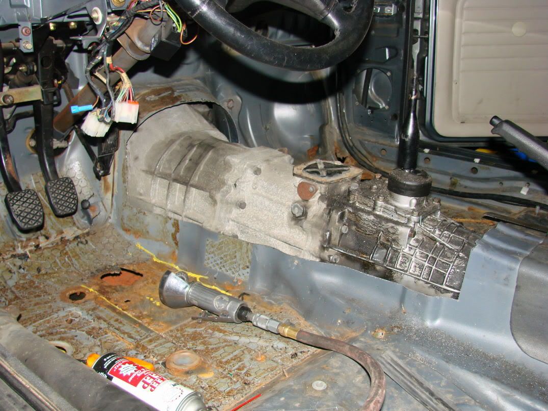 Tomorrow (or friday) I'll be finishing the trimming and building a transmission mount. We decided that since so much material was removed from the unibody, we are going to run some extra bolt-on stiffeners under the transmission. Oh, and this came:  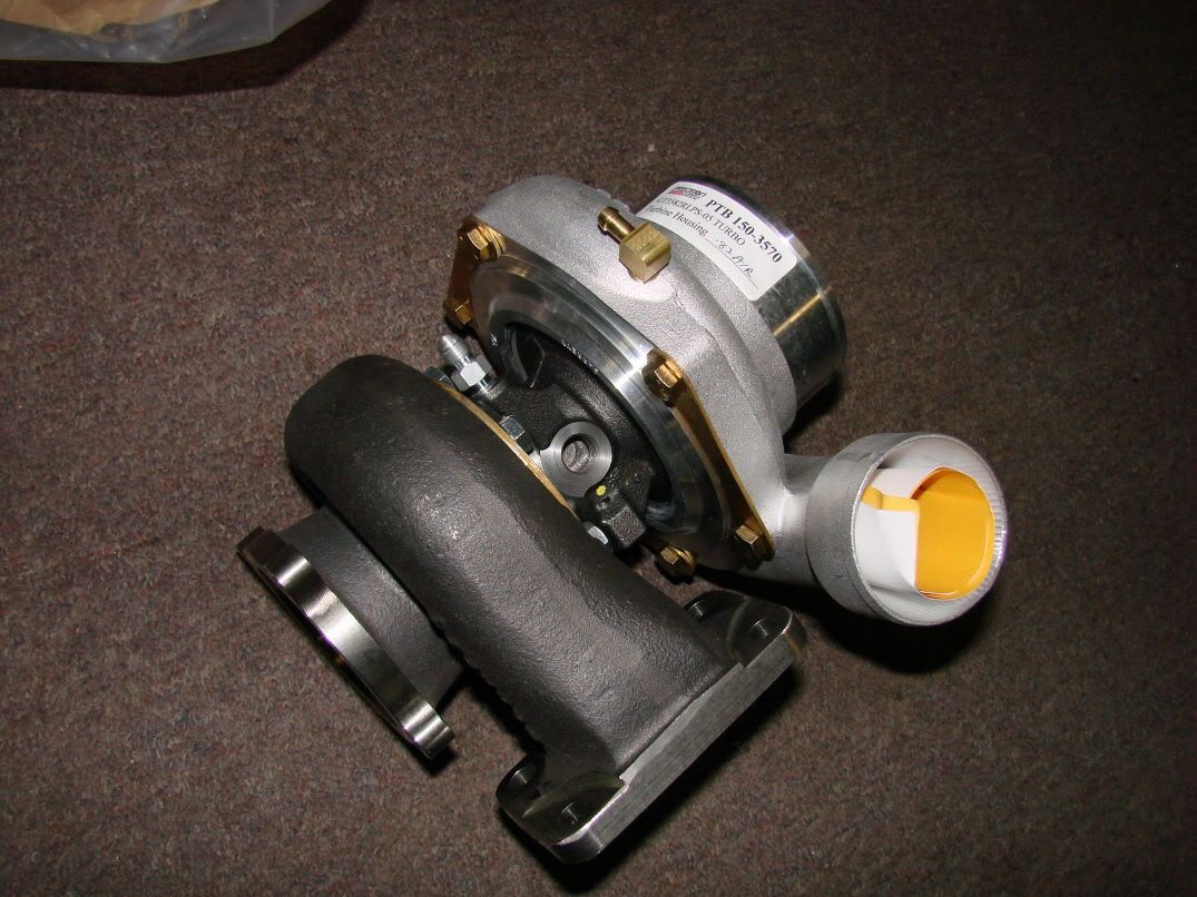 |
|
|
|
|
01-17-2007, 11:36 PM
|
#68 |
|
Join Date: Feb 2006
Location: Palmy New Zealand
Posts: 23
Trader Rating: (0)
Feedback Score: 0 reviews
|
Are you leaving the center diff on the side of the gearbox? By looking at some of the fab stuff you have done so far I doubt it will be a big deal for you to remove it and patch the box housing back up again.
|
|
|
|
|
01-18-2007, 12:01 AM
|
#70 | |
|
Post Whore!
Join Date: Jul 2006
Location: SòCal♥
Age: 38
Posts: 5,840
Trader Rating: (1)
Feedback Score: 1 reviews
|
Quote:
what a Deal, Damn that is so sick. I want to get a bmw, but its between yours, and a 99 e39 for DD
__________________
Robby Leuer 
|
|
|
|
|
|
01-18-2007, 06:58 AM
|
#71 | |
|
Zilvia Junkie
Join Date: Apr 2004
Location: buffalo,ny
Age: 43
Posts: 541
Trader Rating: (0)
Feedback Score: 0 reviews
|
Quote:
the logistics of removing it are actually rather intricate. the drive chain actually feeds an internal oil pump in the form of splash lubrication. BUT, it's kind of in the way of the exhaust at the moment. i'm debating whether or not to remove it... as seen below, the drive chain dumps oil into the strainer assembly which feeds the oil pump... I just don't know what the oil pump is feeding... |
|
|
|
|
|
01-18-2007, 12:29 PM
|
#74 |
|
Zilvia.net Advertiser

Join Date: Nov 2005
Location: Michigan
Age: 37
Posts: 5,616
Trader Rating: (16)
Feedback Score: 16 reviews
|
I'm loving the high-mount shifter! seriously. Nice work in general.
__________________
Build: http://zilvia.net/f/showthread.php?t=643065 Friends don't let friends buy knock-offs. |
|
|
|
|
01-19-2007, 08:29 AM
|
#76 |
|
Zilvia Junkie
Join Date: Apr 2004
Location: buffalo,ny
Age: 43
Posts: 541
Trader Rating: (0)
Feedback Score: 0 reviews
|
last night's progress...
Cut the rest of the tunnel out (another 1" from the rear) and was able to bolt up the transmission. It fits nicely, there is no need to remove or even move the engine to access the transmission bolts... That's a great feature. Especially for anyone who has ever tried to change the transmission on a 300ZX... I made a temporary tranny mount out of this prybar: 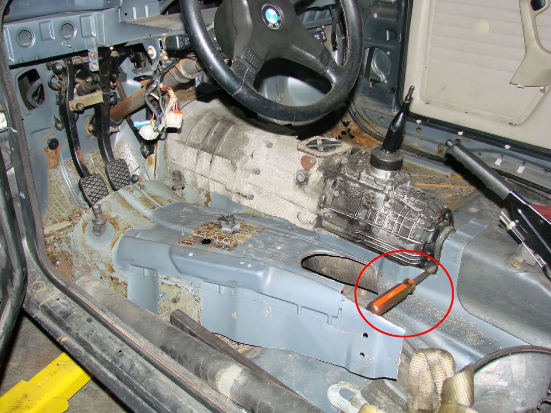 Here are a few shots of the trans in the car: 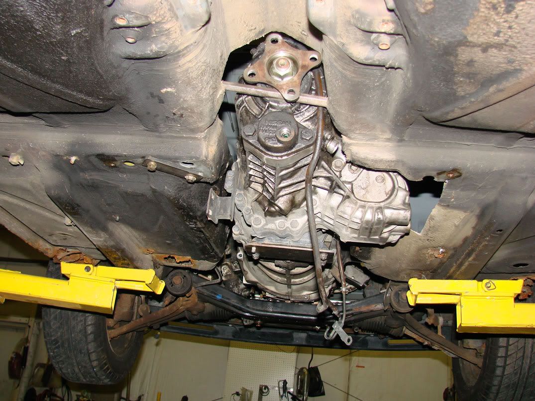 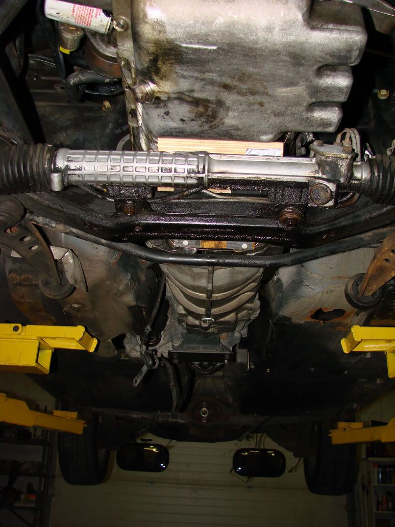 Next, I began planning a transmission mount. The first step was to make bolting plates. You can see the two i made here: 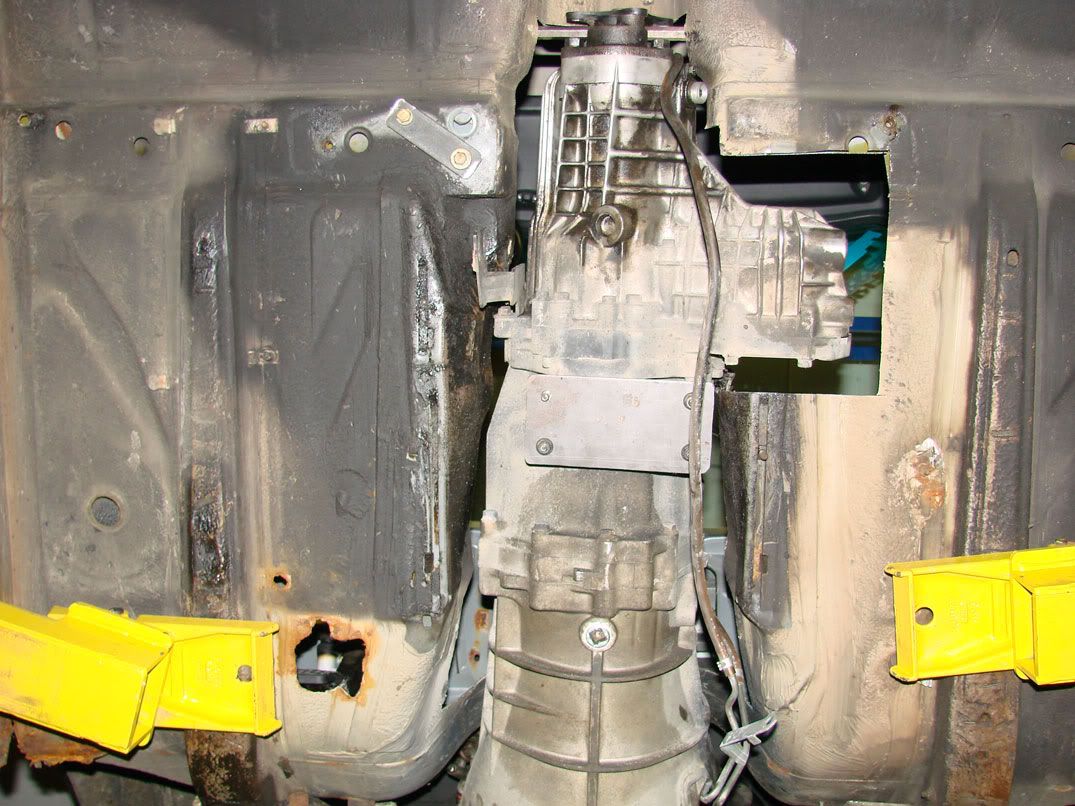 The main transmission bolting plate is made from 7GA Mild steel. You can see it bolted to the rubber transmission mount. We decided on keeping the stock rubber trans mount, despite the fact that we are using solid engine mounts. Need to have some compliance somewhere! The other bolting plate picks up the two bolts for the stock transmission mount. Notice the distance from the rubber trans mount to the stock location. Since the transmission utilizes the rubber mount, simply joining the rubber mount to the stock location would result in a point loaded cantilever beam. The chassis is not meant to maintain such loading especially at a point that has already been compromised by tunnel modifications, so an alternate solution, or a dual cantilever beam must be incorporated. As I mentioned a few days ago, since so much material was removed from the tunnel, a support brace would be desired. This brace was to be located midway down the tunnel, underneath the transmission. Since the forward face of the rubber mount on the transmission is about midway back on the tunnel, it was decided that a transmission mount/chassis brace "subframe" could be constructed. Bolting plates will be welded to the chassis floor, then the "subframe" will be bolted to that. Here is an artist's rendition of the proposed solution: 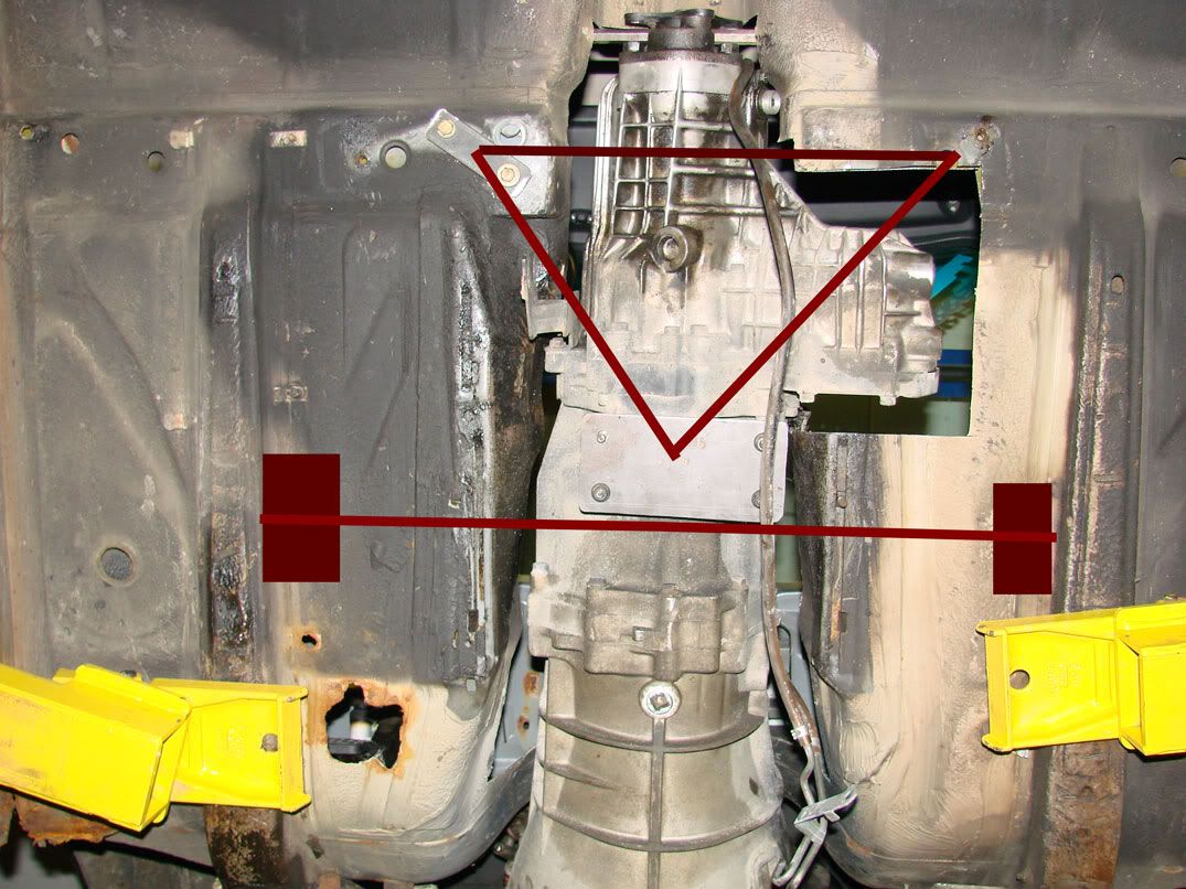 |
|
|
|
|
01-23-2007, 12:27 PM
|
#77 | |||
|
Zilvia Junkie
Join Date: Apr 2004
Location: buffalo,ny
Age: 43
Posts: 541
Trader Rating: (0)
Feedback Score: 0 reviews
|
Alright, since don posted the pictures, i will explain them.
The first thing i did when i arrived was make the rest of the bolting tabs for the transmission mount. These were fabricated from 1/4 X 1 1/4 HRS flat stock. There were a total of four. The center plate is 10GA Mild steel. I obtained some 1 X 1 X 11GA square tube to use for the frame. The next step was to fix the rear passenger transmission mount point. As you can see in this old picture, one of the mounting bolt holes (upper right) was removed to to allow for clearance of the differential. The manner in which the floor was cut allowed access to the area near where the nut had been, so i simply drilled a hole and tacked a nut in place. I then sprayed everything with primer to prevent rusting. Done. 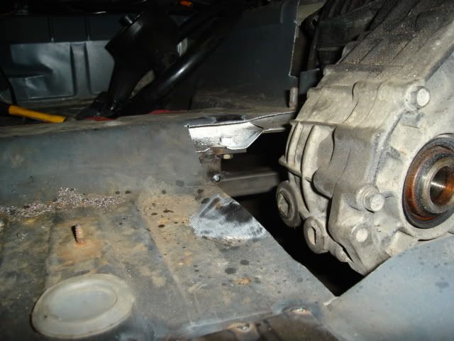 Next, I fabricated the front of the transmission support. This support is also an integral chassis member, as a substantial amount of rigidity has been lost when the formed tunnel was removed. Since there will be substantial stress on the member, it was important to have it bolt to a substantial support. The solution was to weld 7GA plate on the inside of the chassis. The location of the plates is such that the outside edge of the support is actually welded to the "frame rails" of the car. The steel is a pain in the ass to weld on, and welds like crap. I am not the best welder, or even decent, but there is something in the chassis that makes it very "spattery". I cleaned the metal VERY thoroughly. On the passenger's side, the floor was very solid. This is the plate i welded in: 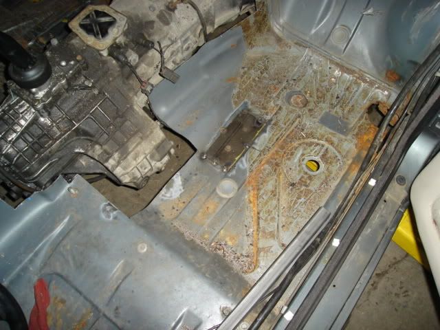 On the driver's side, the floor had been compromised a bit more by rust, so i used two plates. A slight bend was required and with no brake in sight, i used a seam as opposed to a bend. Before tacking these in place, I used a wire wheel to grind off ALL the rust underneath the plates. I still need grind off the undercoating before welding it. I started laying a bead and almost asphyxiated. Photo of the driver's side: 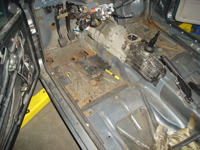 Next, i simply just welded up the frame. Some slight changes had to be made from the initial plan. These changes allow for better clearance, both ground and transmission. I still need to weld on two more braces that tie the mounting points together fore and aft. Here are pictures: Engine is nice and straight: 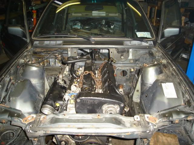 View from the front: 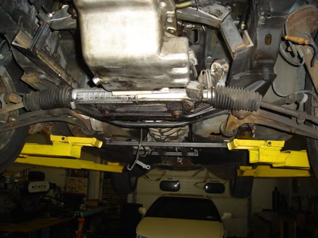 View from the rear: 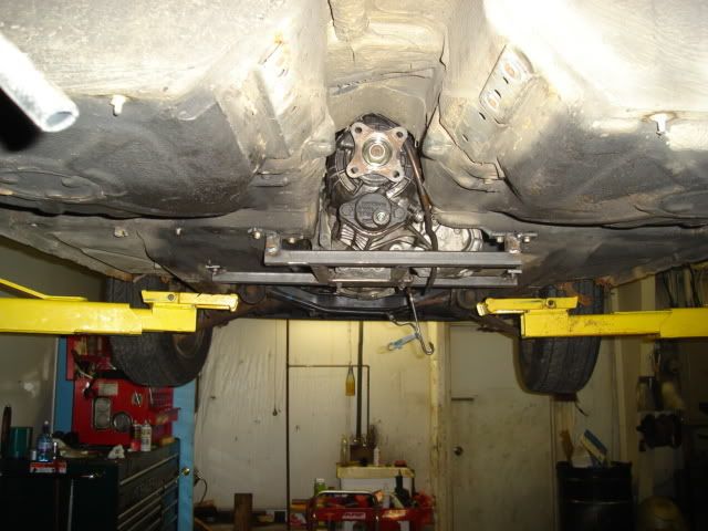 View from underneath: 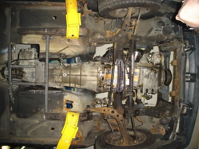 Some research yielded information about driveshaft angles. The motor was moved up slightly from it's original position to allow for a closer driveline angle. The rear differential may need some slight shimming so it points upwards slightly more, but all in all, it is very close to perfect. Answers to questions: Quote:
Quote:
Quote:
|
|||
|
|
|
|
01-23-2007, 08:24 PM
|
#78 |
|
Zilvia FREAK!
Join Date: Dec 2006
Location: tampa bay, fl
Age: 42
Posts: 1,042
Trader Rating: (2)
Feedback Score: 2 reviews
|
seems like somemuch overengineering to fit a awd trans that you arent gonna use. i see no upside to this. you had to spend all this time, you had to cut up the floor more, you are loosing floor room for the poor passenger, and you have all th extra weight of the transfer case haning off there.
i understand you had this trans already, but i think it the long run it would have been better to just source a rwd trans. |
|
|
|
|
01-24-2007, 06:40 AM
|
#80 | ||||
|
Zilvia Junkie
Join Date: Apr 2004
Location: buffalo,ny
Age: 43
Posts: 541
Trader Rating: (0)
Feedback Score: 0 reviews
|
Quote:
An rb25 trans is over a grand, approaching 1500. The only thing would not have to be cut would be the floor, it's still the same height, the whole tunnel still would have to be cut out. the passenger won't even notice the transfer case there. Quote:
upside #2: I know this transmission is good. I pulled it off of a GTR that I had driven upside #3: Have you tried buying an RB25 trans? They are not easy to find. Quote:
Quote:
I'm just getting frustrated with everyone bitching about my use of the RB26 trans. But, for all the haters, I am cutting the transfer case off today... |
||||
|
|
|
|
01-24-2007, 06:15 PM
|
#82 |
|
Zilvia FREAK!
Join Date: Dec 2006
Location: tampa bay, fl
Age: 42
Posts: 1,042
Trader Rating: (2)
Feedback Score: 2 reviews
|
im not a "hater" at all.
i like what you're doing, and you do quality fabwork from what i have seen so far. im just saying what i would have done. carry on. |
|
|
|
|
01-24-2007, 11:43 PM
|
#84 |
|
Zilvia Junkie
Join Date: Apr 2004
Location: buffalo,ny
Age: 43
Posts: 541
Trader Rating: (0)
Feedback Score: 0 reviews
|
here's today and yesterday's updates. I apologize for typos. More on this later...
Yesterday: Added another brace to the crossmember. This triangulates the subframe and i am convinced it is now strong enough. My welding leaves much to be desired... I need to work on this much more... Next, pulled the transmission back out of the car and unbolted the transfer case. I took everything out of it. This is what was left. 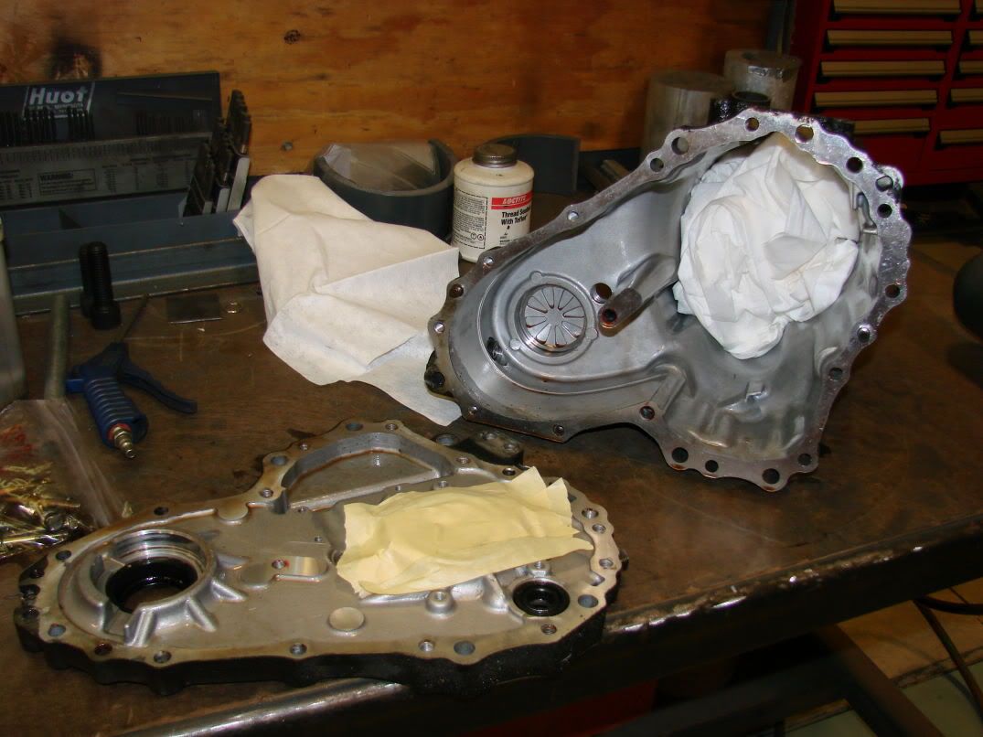 Then i went home. Today: Went to the shop after work. I taped off the bearings to avoid contamination and bolted the gutted transfer case back together. I then used the horizontal band saw and cut the output case off of the transfer case. 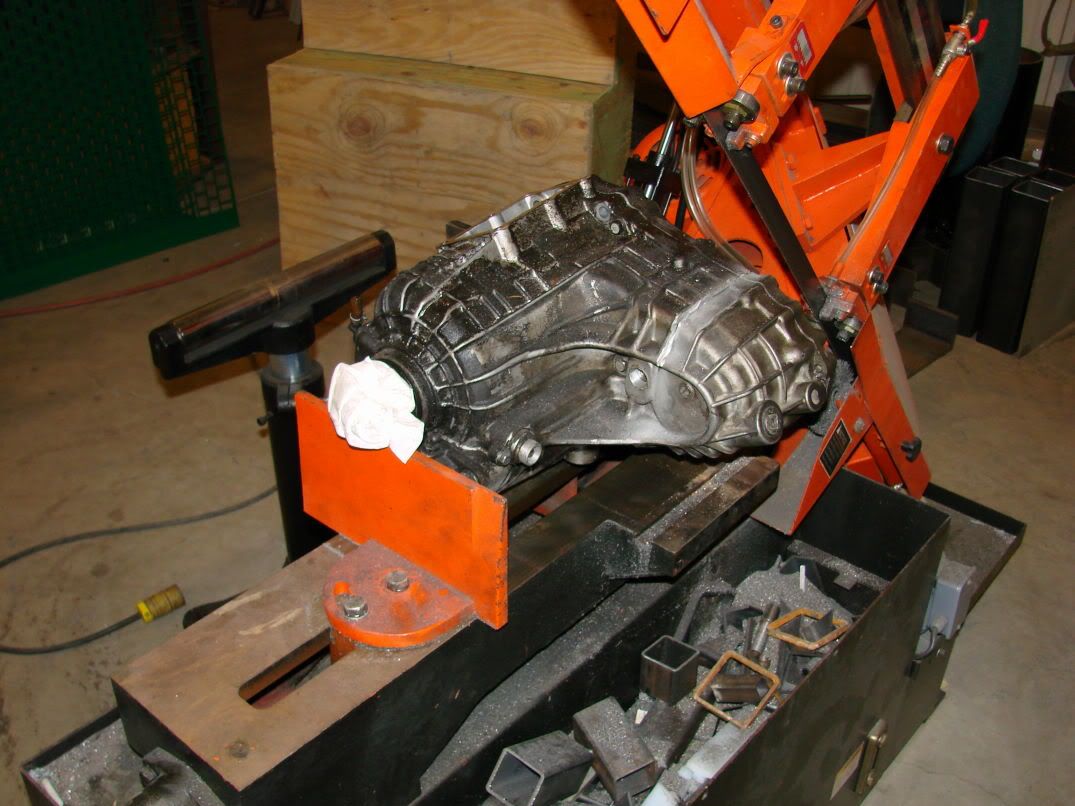 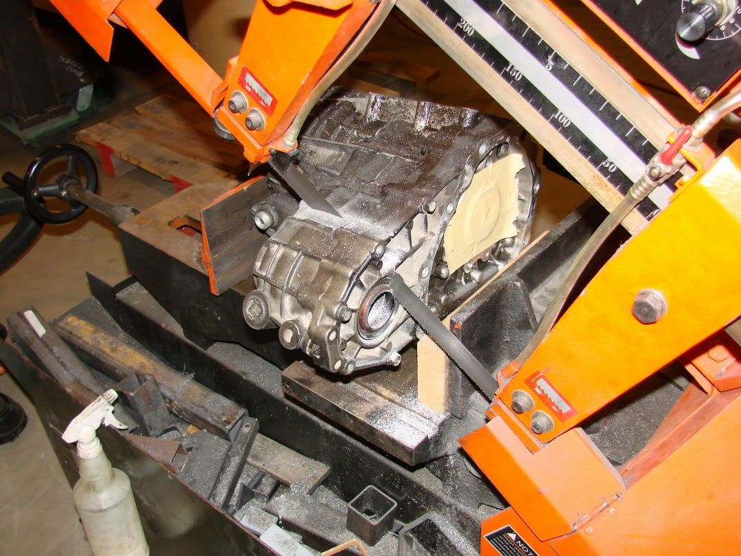 This step went remarkably smoothly. The result:  Next i mounted the transfer case on the milling table I was only able to get 2 mounting points, one of which was a bit "shady" but I hit it with a rubber mallet after i bolted it down, and it didn't budge. The tool in the mill is not the tool i used (i used a 2.5 inch facing tool) I used a level and shims to get the case mounted correctly. The location of the face didn't need to be that precise, so a level was fine: 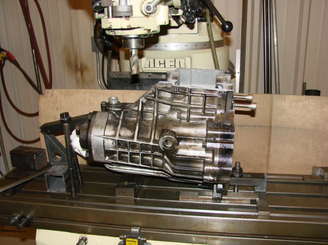 Next, i made pass after pass on the part, taking off about .100 per pass. About an hour later I had a flat surface, about an inch shorter than the above picture. (sorry, no pic) At some point during this, the tape over the bearings gave way and a shit-ton of aluminum chips made their way into the front bearing. I will try my best to get them out of there with a parts washer/ air gun, but i may need to suck it up and buy a new bearing. Meh, live and learn, I should have taken it out first, instead of trying to take the easy way out and "cover" it. Also at some point during this, i somehow managed to crush my hand between the workpiece and the tooling. I had to pick bits of fingernail off the tooling. EW. 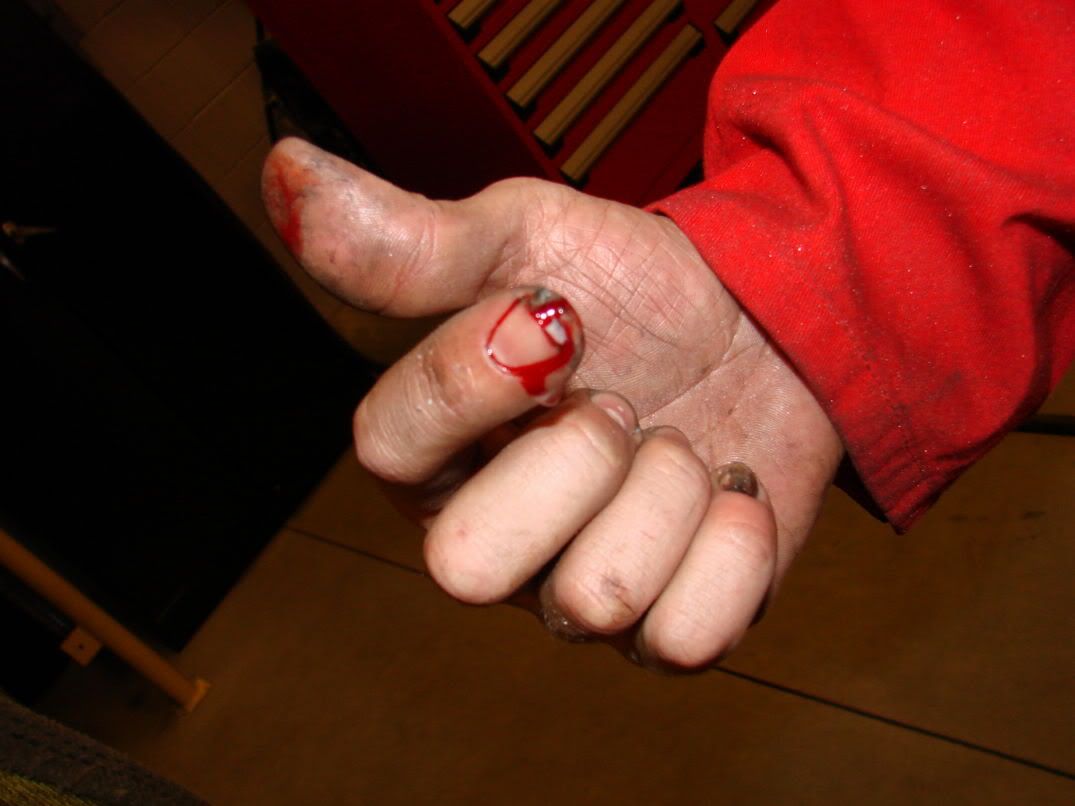 Now that the face was complete, i chucked up a drill and drilled (11) #21 holes X .9 deep along the perimeter of the face. Then using a hand tap, i tapped the holes to 10-32 thread. A hand tap was a bad idea, i should have used the mill to guide the tap, as one of the bolts went in slightly crooked, not a big deal, though. It is not terribly off. The hole that looks like it is "falling off" is intentionally placed there, as it was necessary to avoid an internal bolt. 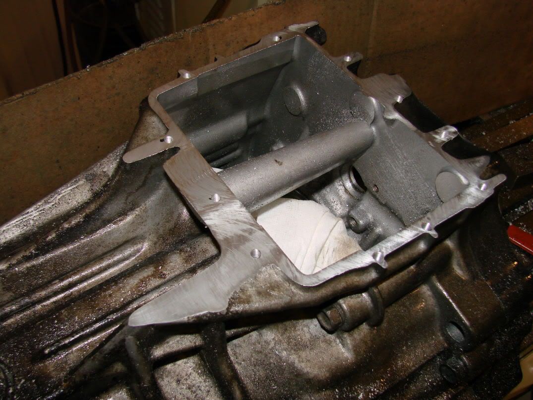 All that was left was too make a cover. Since i had written down the X,Y locations of all the holes i had drilled in the case, it was relatively easy. I used a belt sander and the mill to make the outside perimeter, then after the holes and perimeter were complete, i made a few facing passes on the mating surface of the cover. Due to the fact that the cover was no longer in square, there was a tiinny bit of chatter on the final face, but nothing that wont be sealed with RTV or hondabond. The finished cover and assembly: 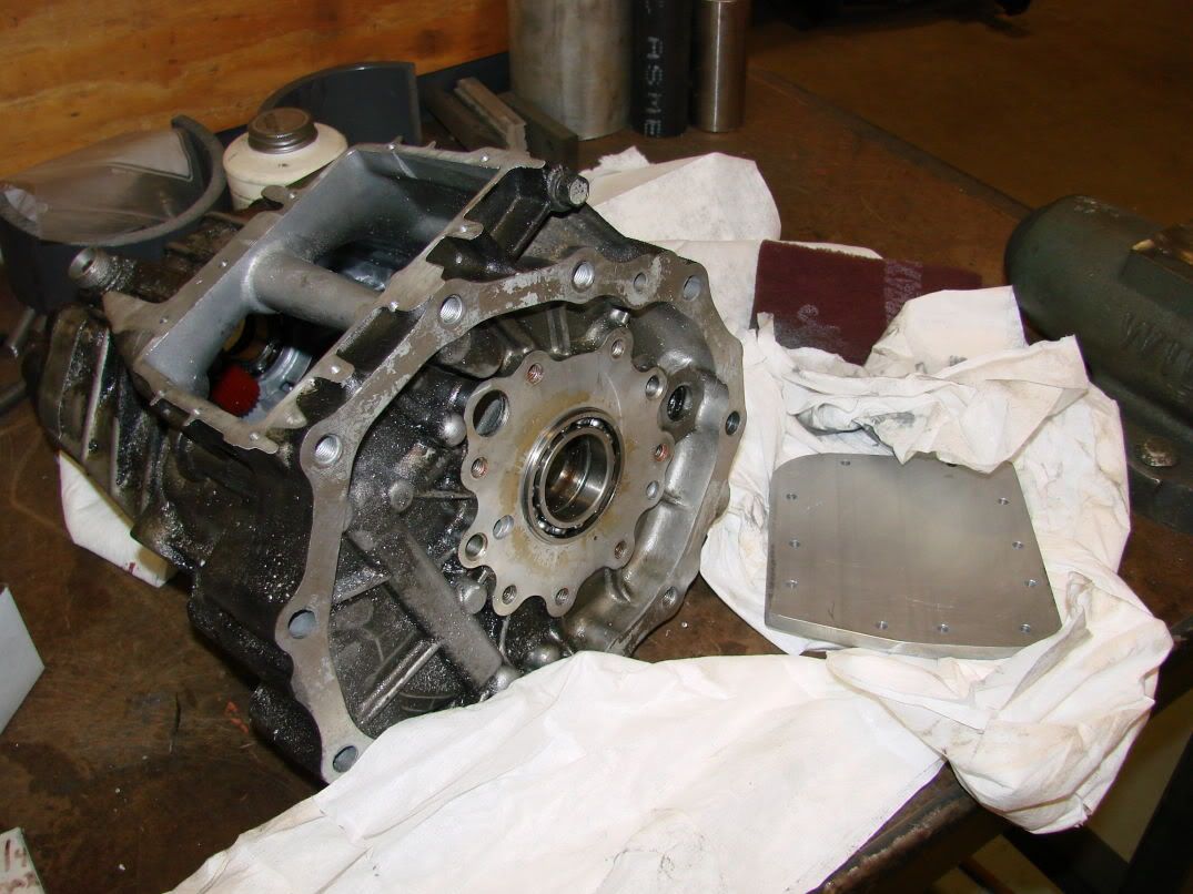 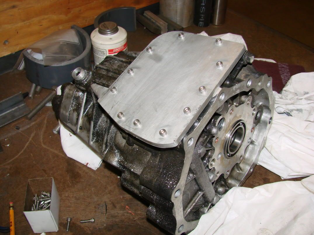 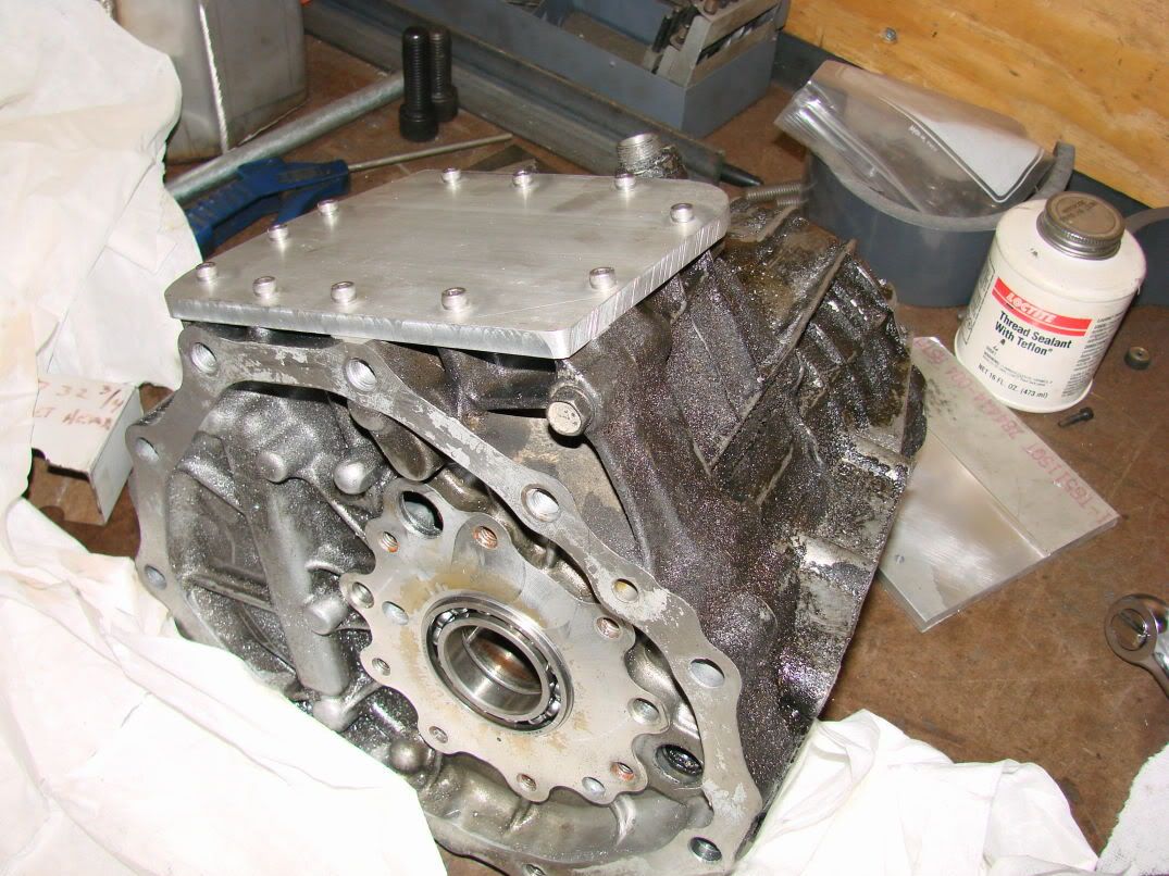 Total time = 6 or 7 hours. Dollar amount saved (vs buying rb25 transmission) = $1500 Weight difference = negligable Now i just need to put it back together. Oh, I also plan on drilling a tapping a few holes on the cut-off portion of the tcase, then using a torque wrench to find out at what torque the threads strip, this will allow me to get a torque value to tighten the hardware to. I will leave you with this picture: 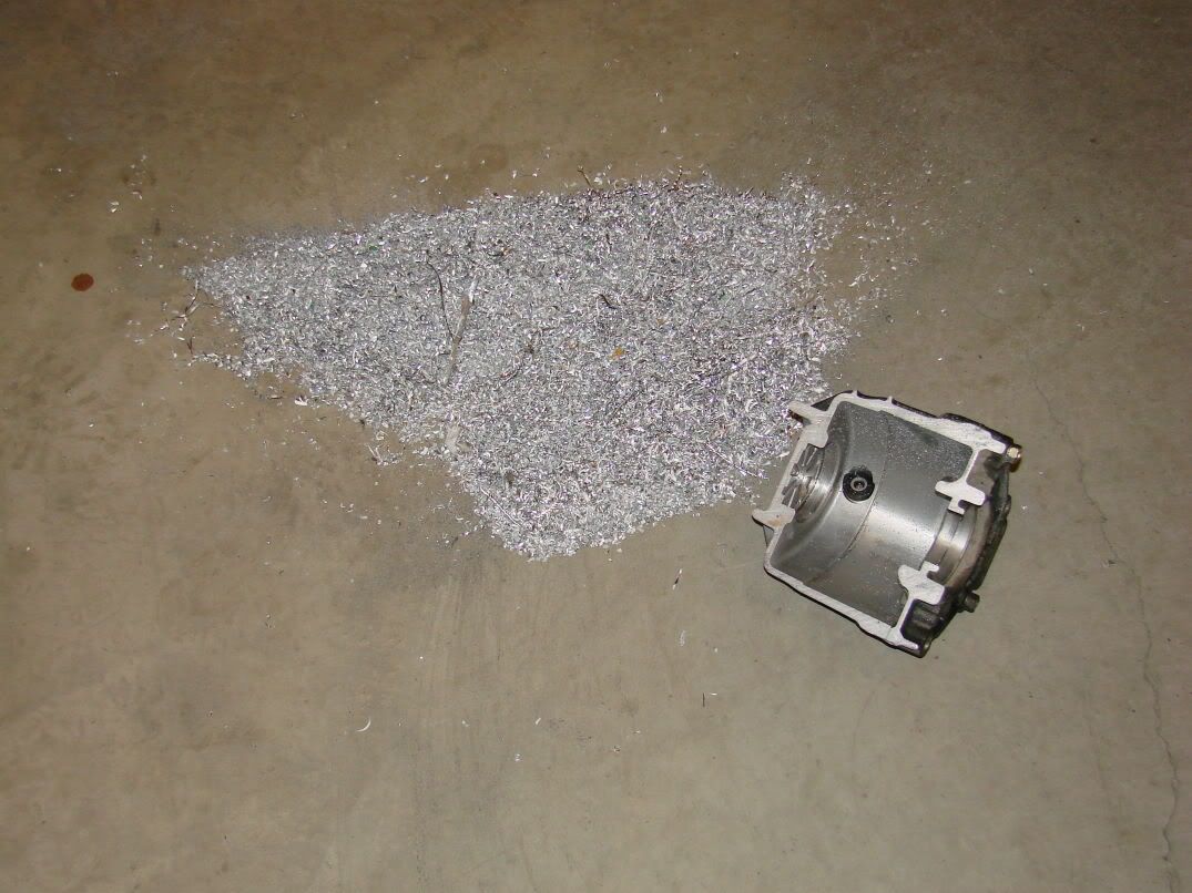 |
|
|
|
|
01-25-2007, 07:37 AM
|
#85 |
|
Post Whore!

Join Date: May 2006
Location: San Diego, CA
Posts: 9,135
Trader Rating: (19)
Feedback Score: 19 reviews
|
Awesome job. Sounds like you've taken an engineering course or 10, which is decidedly rare in machine shops - more props. You're doing a great job with all the fab work, keep doing it right and whoever ends up with that car will thank you, hopefully with their checkbook
__________________
 Jordan Innovations has a new web site! www.JordanInnovations.com -- All your favorite FD Pro Drifters love it, trust me -- www.JordanInnovations.com |
|
|
|
|
01-30-2007, 08:00 AM
|
#86 |
|
Zilvia Junkie
Join Date: Apr 2004
Location: buffalo,ny
Age: 43
Posts: 541
Trader Rating: (0)
Feedback Score: 0 reviews
|
Alright, heres the update for the past few days...
Thursday: Begin assembling transfer case. Friday: Complete transfer case and reassemble transmission. The total savings was a substantial amount of room and about 30lbs of ROTATING mass. Here are pics of the completed transmission. 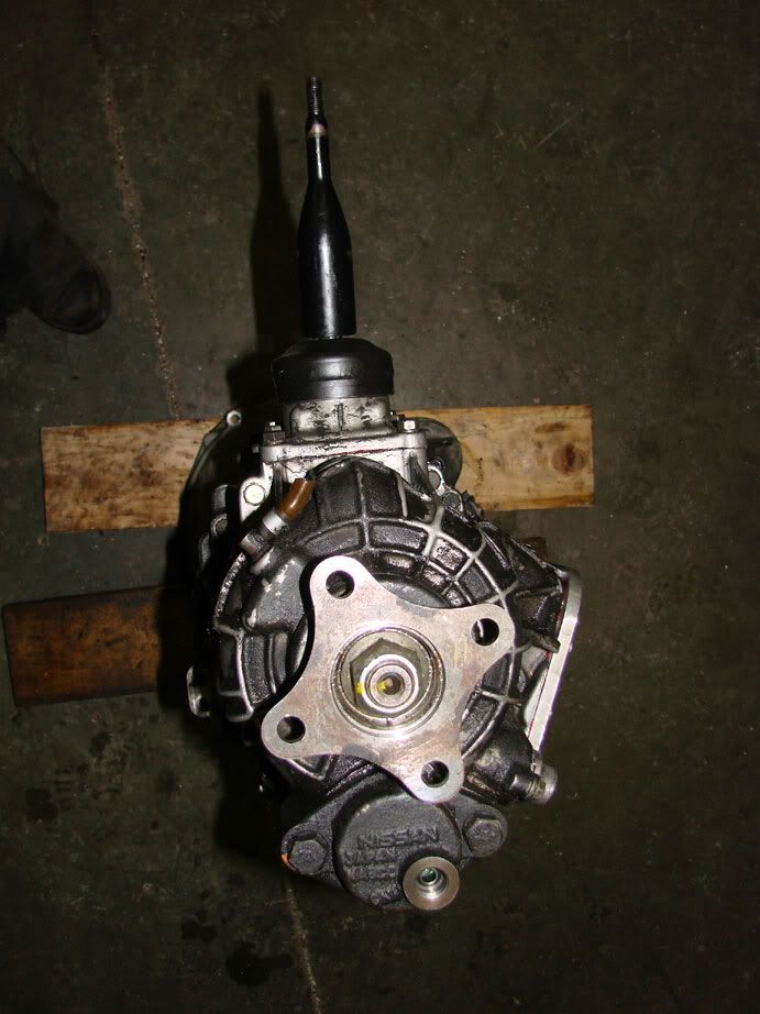 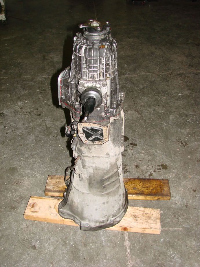 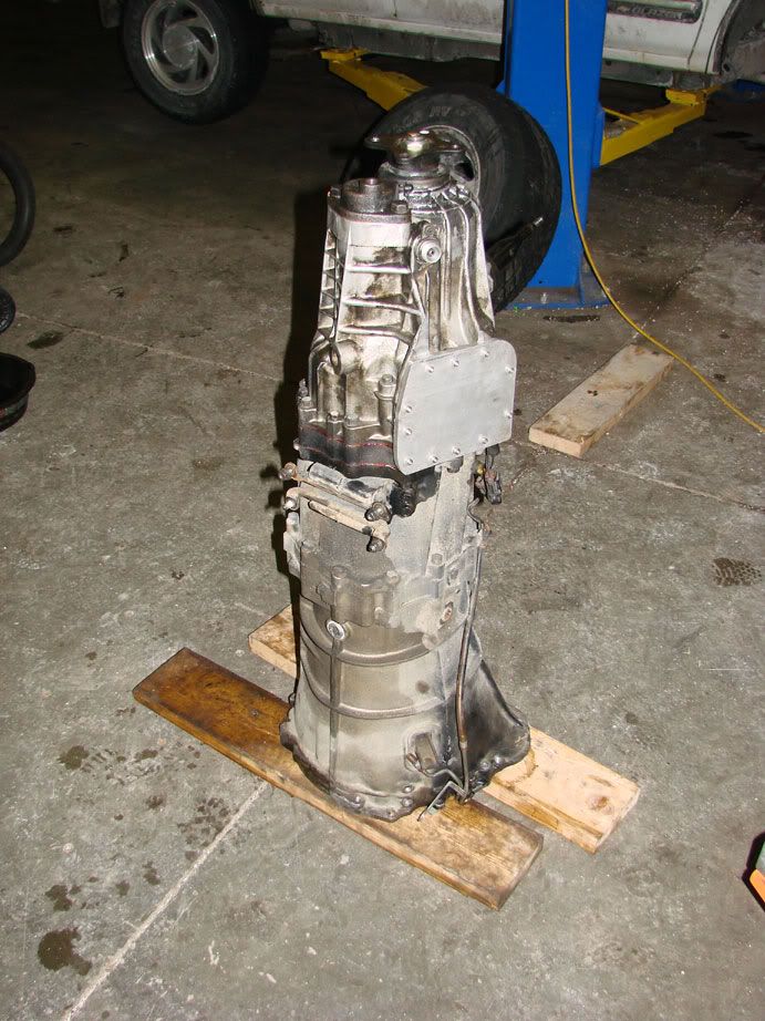 Saturday I began trying to solve the next major hurdle... The brakes. I tried a few things, looked at various brake boosters and master cylinders... What i found to be the most space efficient was a civic master cylinder and booster. I feel confident that this setup will be fine for the street. The car weighs less than a civic EX in full trim, and had plenty of stopping power on layzie's turbo hatch. (In fact, it's layzie's old unit  ). While this setup isn't exactly track-able, it will do for now. I didn't want to blow hundreds of dollars on a tilton setup just yet, because I don't even know the fate of the car, as yet... but I digress. ). While this setup isn't exactly track-able, it will do for now. I didn't want to blow hundreds of dollars on a tilton setup just yet, because I don't even know the fate of the car, as yet... but I digress.Without modifying the civic brake booster at all, I probably could have fit it in place, but the clearance would have been tight. The bolt pattern on the civic unit is a wide rectangle. (3.5 inches wide X 2 inches tall). In order to get the mounting studs to clear the clutch pedal bracketry, I would have to cheat the master cylinder almost an inch TOWARD the motor. Also, the studs on the driver's side of the car would be floating in midair, as they passed through the center hole of the old unit. That's no good. however, if I rotated the booster 90 degrees, the bolt pattern became a tall rectangle (2 wide X 3.5 tall). In this configuration, both of the above problems were solved. The new bolt holes required in the firewall landed on sheetmetal (albeit, not a lot) and not only was i able to "re-center" the booster, but was now able to cheat it about an inch AWAY from the motor. Holla. The next step was to drill the new holes, and clearance the firewall for the snout of the booster. I'm a bit ashamed at how this turned out... I measured twice, carefully drilled the firewall, then tried to fit the booster. What I failed to notice was the clearance for the brake pedal mounting bracket interfered with the studs on the booster, so the whole assembly needed to be shifted around slightly. I was a bit frustrated at this pint, and probably should have called it a day, but i attacked the firewall with a die grinder until it fit. Pic = YUCK! 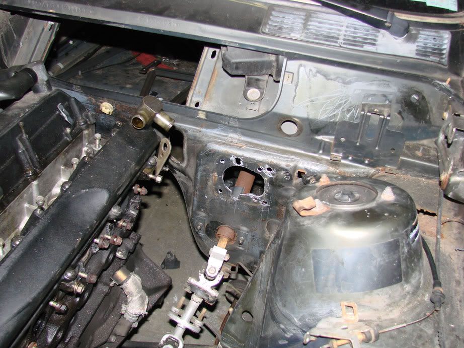 Sunday: Well, now that we had fit the booster at 90 degrees, it was now necessary to rotate the master cylinder BACK 90 degrees. Since the booster is a sealed unit with a rubber diaphragm, welding and/or drilling it was out of the question. My answer to this problem was again the machine shop. Using some 3/8 6061, I fabbed up these brackets in about 3 hours. They allow the master to be mounted at exactly 90 degrees from it's original position. 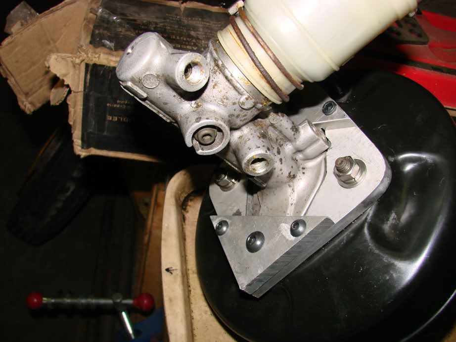 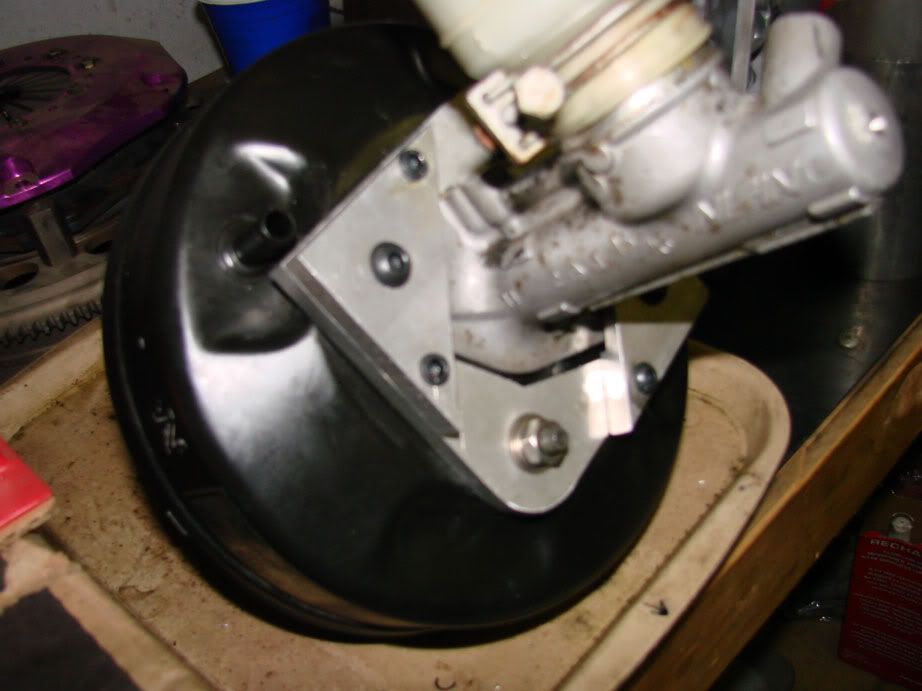 Still a bit embarrassed about my shitty firewall job, i fabbed up this closeoff plate out of 11GA 304SS. The picture is deceiving, but all the edges are perfectly square and all the holes are clean. 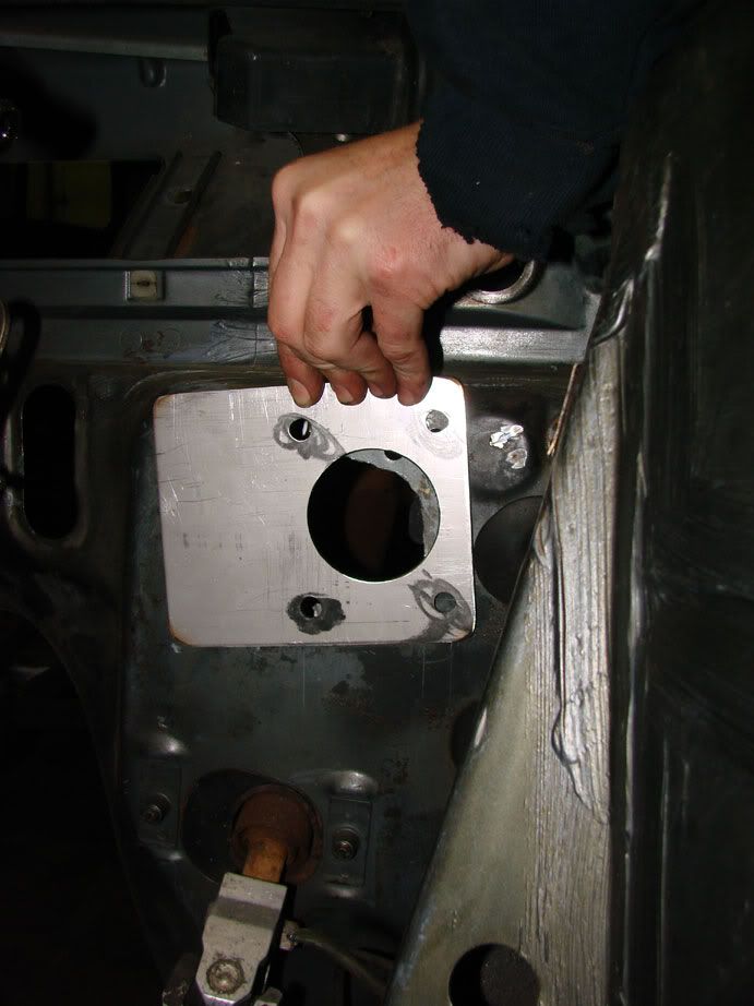 Of course, even without the plate, when everything is installed, you can barely see any of the "hack job", but it's there for my personal peace of mind. As for structural integrity, the brake pedal support, which you cannot see, provides all of the support for the booster assembly. The firewall, even in stock form, provides very little support. Monday: The last step, since the booster (and thus, the actuation shaft) moved OUTBOARD 1", the pedal needed to be modified. I don't have a before picture, but perfectly enough, the OEM pedal actually had a 1" extension INBOARD. I simply cut this off and welded it back on @ 0" extension. 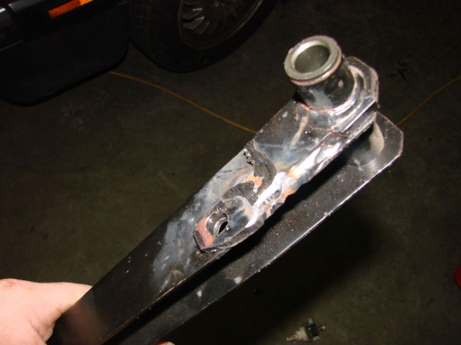 After i bolted everything back together, i tested for smooth feel and travel. Success! We spent the time afterwards relaxing, chilling out and just talking about our feelings. I also performed some preliminary radiator and intercooler fitment analysis... The entertainment of the night was watching Gary (deviousTSi) manhandle his 1G DSM with 4 seized brakes into the shop. It was manly as fuck. 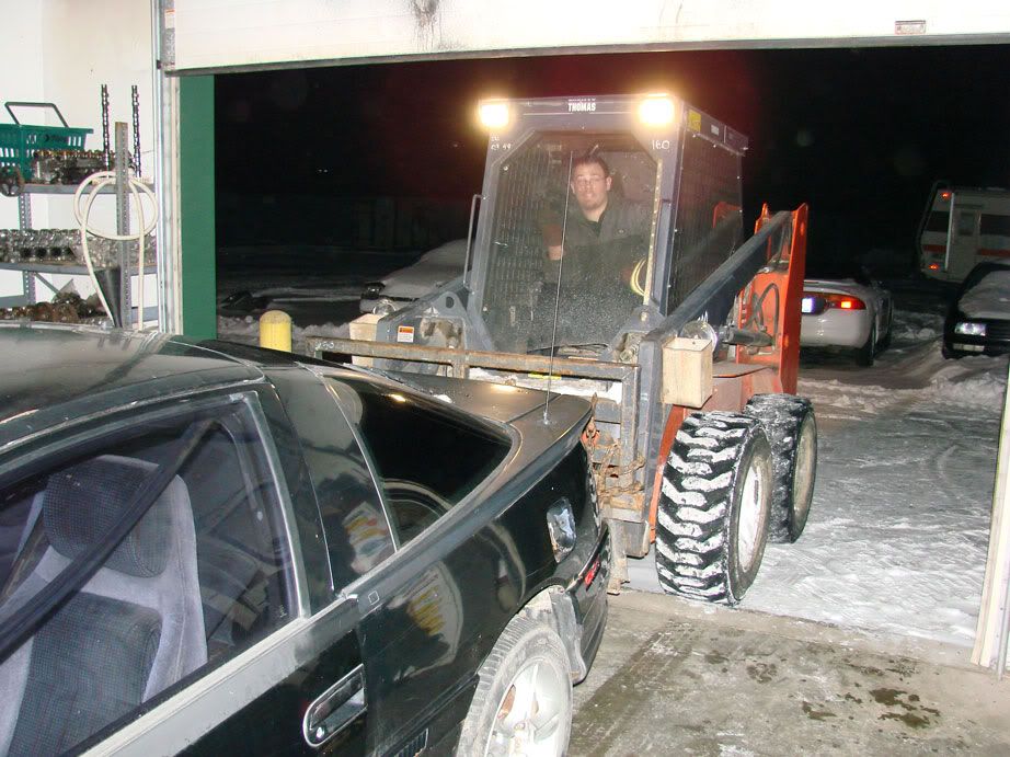 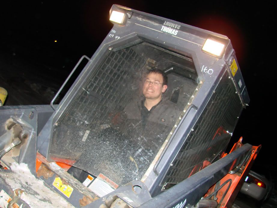 |
|
|
|
|
01-31-2007, 12:05 AM
|
#88 | |
|
Leaky Injector
 Join Date: Sep 2006
Location: norcal
Age: 38
Posts: 110
Trader Rating: (0)
Feedback Score: 0 reviews
|
LOVE the build. Must be nice to have access to a machine shop like that.
Quote:
|
|
|
|
|
|
01-31-2007, 07:27 AM
|
#90 | |
|
Zilvia Junkie
Join Date: Apr 2004
Location: buffalo,ny
Age: 43
Posts: 541
Trader Rating: (0)
Feedback Score: 0 reviews
|
Quote:
hahaha, youtube search these words: "adventure time" make sure you watch to the end... |
|
|
|
|
|
| Bookmarks |
|
|


 ...Nice project good luck with it.
 Nice work.


 Linear Mode

